Open in CAN Main Bus Line
NETWORKING: CAN COMMUNICATION SYSTEM: Open in CAN Main Bus Line
- Open in CAN Main Bus Line
DESCRIPTION
There may be an open circuit in one of the V bus main wires and/or a DLC3 branch wire when the resistance between terminals 6 (CANH) and 14 (CANL) of the DLC3 is 70 Ohms or higher.
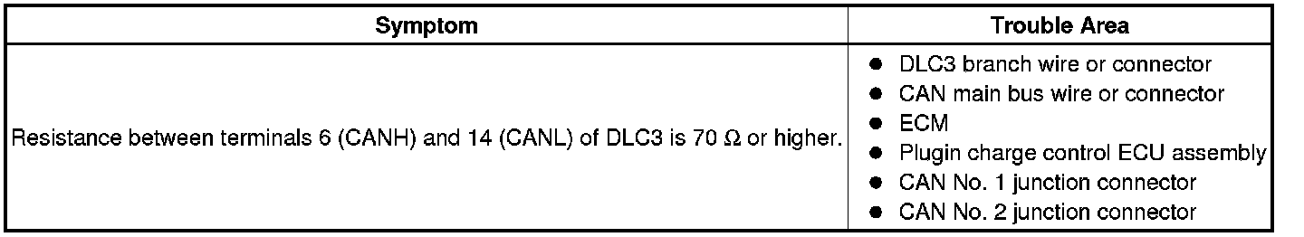
This malfunction is not related to the wires of a CAN main bus branch or to ECUs or sensors connected a CAN main bus branch.
WIRING DIAGRAM
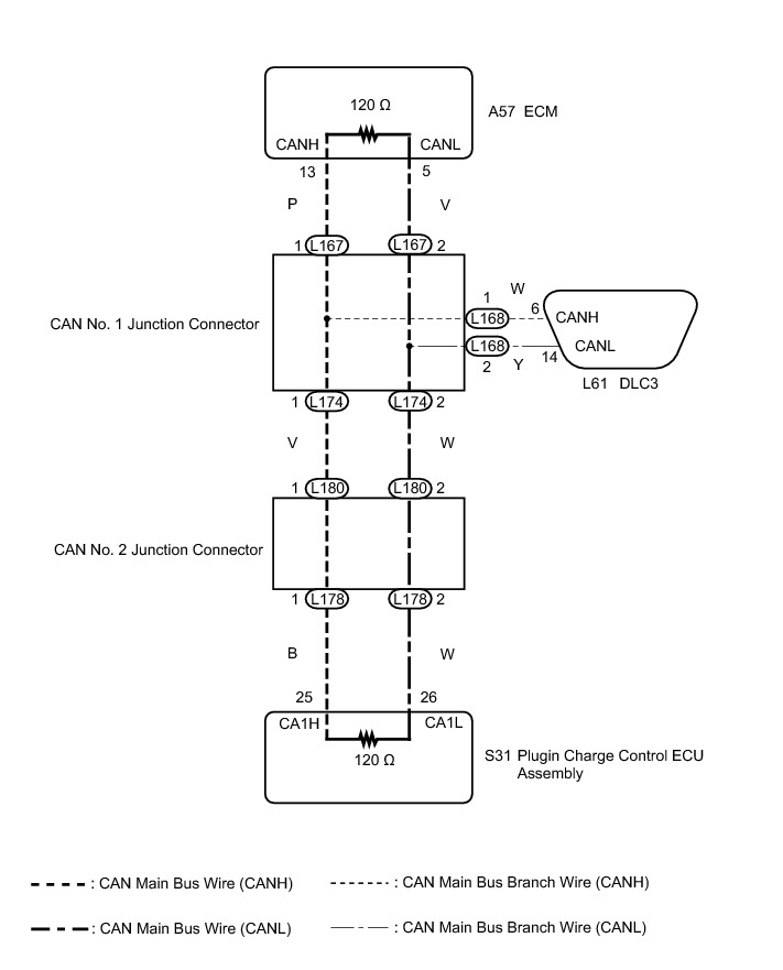
INSPECTION PROCEDURE
NOTICE:
* Turn the power switch off before measuring the resistances between CAN main bus wires and between CAN main bus branch wires.
* Turn the power switch off before inspecting CAN bus wires for a ground short.
* After the power switch is turned off, check that the key reminder warning system and light reminder warning system are not operating.
* Before measuring the resistance, leave the vehicle as is for at least 1 minute and do not operate the power switch, any other switches or the doors. If any doors need to be opened in order to check connectors, open the doors and leave them open.
HINT
* Operating the power switch, any other switches or a door triggers related ECU and sensor communication on the CAN. This communication will cause the resistance value to change.
* Even after DTCs are cleared, if a DTC is stored again after driving the vehicle for a while, the malfunction may be occurring due to vibration of the vehicle. In such a case, wiggling the ECUs or wire harness while performing the inspection below may help determine the cause of the malfunction.
PROCEDURE
1. CHECK FOR OPEN IN CAN BUS WIRES (DLC3 BRANCH WIRE)
(a) Disconnect the cable from the negative (-) auxiliary battery terminal.
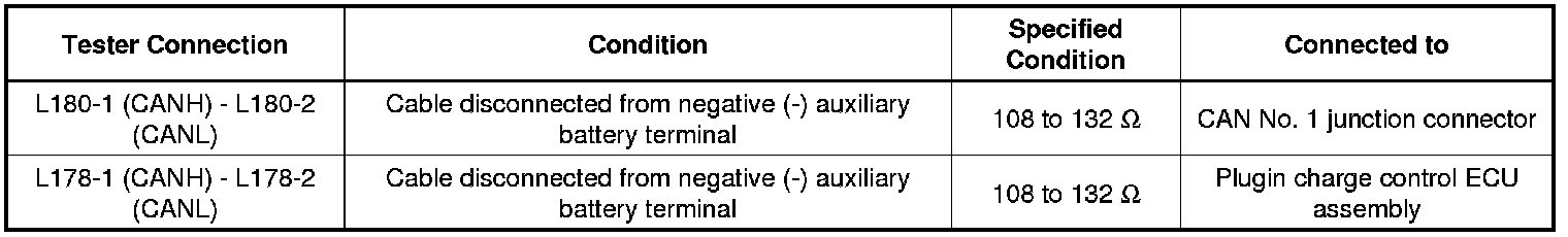
(b) Measure the resistance according to the value(s) in the table below.

Standard Resistance:

Text in Illustration
NOTICE:
When the measured value is 133 Ohms or higher and a CAN communication system DTC is output, there may be a fault besides disconnection of the DLC3 branch line. For that reason, troubleshooting should be performed again from How to Proceed with Troubleshooting after repairing the trouble area How to Proceed With Troubleshooting.
NG -- REPAIR OR REPLACE CAN MAIN BRANCH WIRES CONNECTED TO DLC3
OK -- Continue to next step.
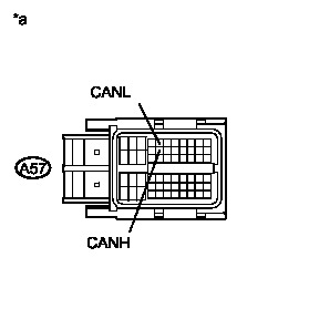
2. CHECK FOR OPEN IN CAN BUS WIRES (ECM - CAN NO. 1 J/C)
(a) Disconnect the ECM connector.
(b) Measure the resistance according to the value(s) in the table below.
Standard Resistance:

Text in Illustration
NG -- CHECK FOR OPEN IN CAN BUS WIRES (PLUG-IN CHARGE CONTROL ECU ASSEMBLY - CAN NO. 2 J/C)
OK -- REPLACE ECM Removal
3. CHECK FOR OPEN IN CAN BUS WIRES (PLUG-IN CHARGE CONTROL ECU ASSEMBLY - CAN NO. 2 J/C)
(a) Reconnect the ECM connector.
(b) Disconnect the plug-in charge control ECU assembly connector.

(c) Measure the resistance according to the value(s) in the table below.
Standard Resistance:

Text in Illustration
NG -- CHECK FOR OPEN IN CAN BUS WIRES (CAN NO. 2 J/C)
OK -- REPLACE PLUG-IN CHARGE CONTROL ECU ASSEMBLY Removal
4. CHECK FOR OPEN IN CAN BUS WIRES (CAN NO. 2 J/C)
(a) Reconnect the plug-in charge control ECU assembly.
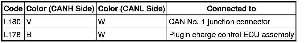
(b) Disconnect the CAN No. 2 junction connectors (L180 and L178).
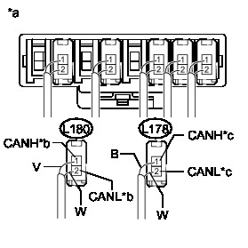
(c) Measure the resistance according to the value(s) in the table below.
Standard Resistance:
Wiring Color:
Text in Illustration
NOTICE:
* Before disconnecting the connectors, make a note of where they are connected.
* Reconnect each connector to its original position.
Result:
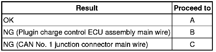
B -- REPAIR OR REPLACE CAN MAIN BUS WIRE OR CONNECTOR (CAN NO. 2 J/C - PLUG-IN CHARGE CONTROL ECU ASSEMBLY)
C -- CHECK FOR OPEN IN CAN BUS WIRES (CAN NO. 1 J/C)
A -- REPLACE CAN NO. 2 JUNCTION CONNECTOR
5. CHECK FOR OPEN IN CAN BUS WIRES (CAN NO. 1 J/C)
(a) Reconnect the CAN No. 2 junction connectors (L180 and L178).
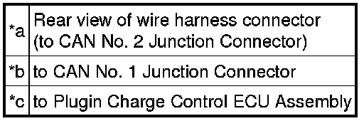
(b) Disconnect the CAN No. 1 junction connectors (L174 and L167).
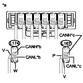
(c) Measure the resistance according to the value(s) in the table below.
Standard Resistance:
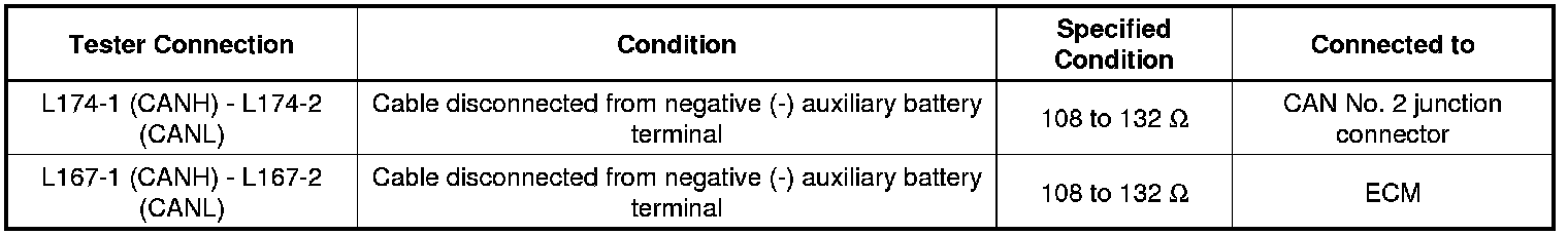
Wiring Color:
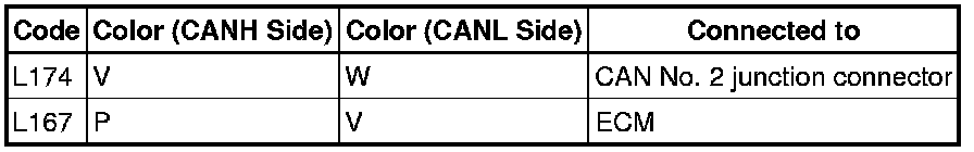
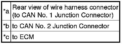
Text in Illustration
NOTICE:
* Before disconnecting the connectors, make a note of where they are connected.
* Reconnect each connector to its original position.
Result:
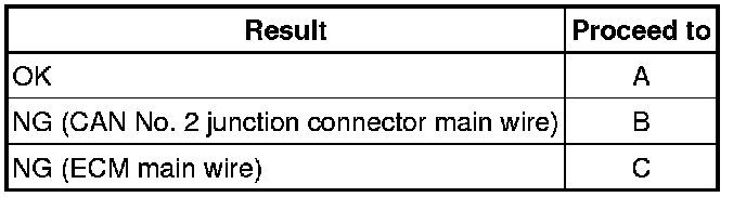
B -- REPAIR OR REPLACE CAN MAIN BUS WIRE OR CONNECTOR (CAN NO. 2 J/C - CAN NO. 1 J/C)
C -- REPAIR OR REPLACE CAN MAIN BUS WIRE OR CONNECTOR (CAN NO. 1 J/C - ECM)
A -- REPLACE CAN NO. 1 JUNCTION CONNECTOR