Fuel Injector Circuit
1NZ-FE ENGINE CONTROL: SFI SYSTEM (for Sedan): Fuel Injector Circuit
- Fuel Injector Circuit
DESCRIPTION
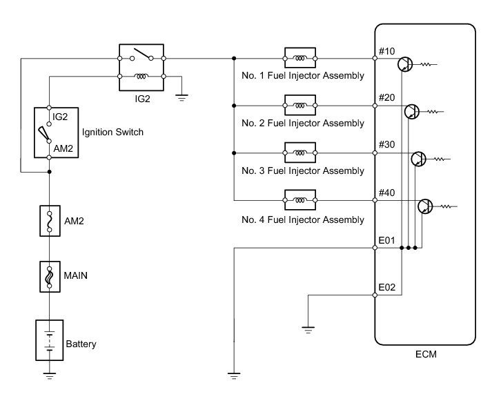
The fuel injector assembly inject fuel based on the signals from the ECM.
WIRING DIAGRAM
INSPECTION PROCEDURE
NOTICE:
Inspect the fuses for circuits related to this system before performing the following inspection procedure.
PROCEDURE
1. INSPECT FUEL INJECTOR ASSEMBLY (POWER SOURCE)
(a) Disconnect the fuel injector assembly connectors.
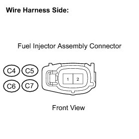
(b) Turn the ignition switch to ON.
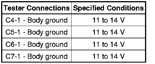
(c) Measure the voltage according to the value(s) in the table below.
Standard voltage:
(d) Reconnect the fuel injector assembly connectors.
NG -- CHECK HARNESS AND CONNECTOR (FUEL INJECTOR ASSEMBLY - INTEGRATION RELAY)
OK -- Continue to next step.
2. INSPECT FUEL INJECTOR ASSEMBLY (INJECTOR RESISTANCE)
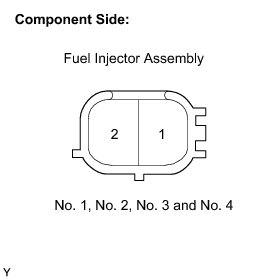
(a) Disconnect the fuel injector assembly connectors.
(b) Measure the resistance according to the value(s) in the table below.
Standard resistance:
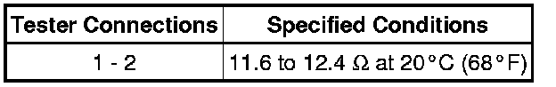
(c) Reconnect the fuel injector assembly connectors.
NG -- REPLACE FUEL INJECTOR ASSEMBLY Removal
OK -- Continue to next step.
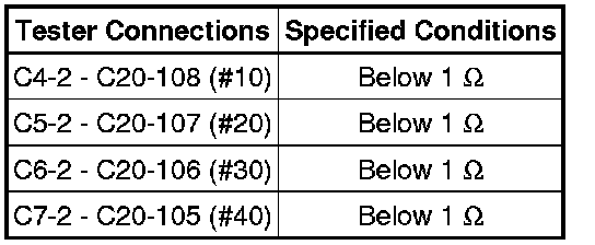
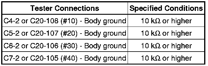
3. CHECK HARNESS AND CONNECTOR (FUEL INJECTOR ASSEMBLY - ECM)
(a) Disconnect the C20 ECM connector.
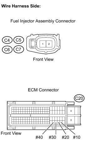
(b) Disconnect the fuel injector assembly connectors.
(c) Measure the resistance according to the value(s) in the table below.
Standard resistance (Check for open):
Standard resistance (Check for short):
(d) Reconnect the fuel injector assembly connectors.
(e) Reconnect the ECM connector.
NG -- REPAIR OR REPLACE HARNESS OR CONNECTOR
OK -- Continue to next step.
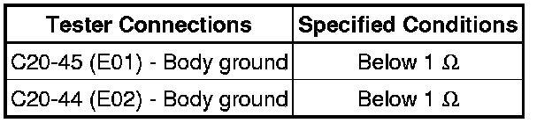
4. CHECK HARNESS AND CONNECTOR (ECM - BODY GROUND)
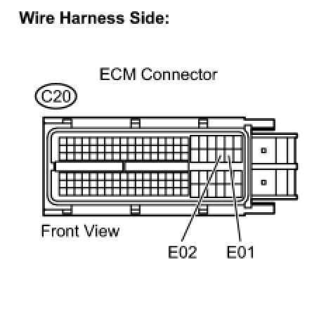
(a) Disconnect the C20 ECM connector.
(b) Measure the resistance according to the value(s) in the table below.
Standard resistance (Check for open):
(c) Reconnect the ECM connector.
NG -- REPAIR OR REPLACE HARNESS OR CONNECTOR
OK -- Continue to next step.
5. INSPECT FUEL INJECTOR ASSEMBLY (INJECTION AND VOLUME)
(a) Check the fuel injector injection and volume Testing and Inspection.
NG -- REPLACE FUEL INJECTOR ASSEMBLY Removal
OK -- PROCEED TO NEXT SUSPECTED AREA SHOWN IN PROBLEM SYMPTOMS TABLE Symptom Related Diagnostic Procedures
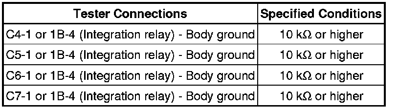
6. CHECK HARNESS AND CONNECTOR (FUEL INJECTOR ASSEMBLY - INTEGRATION RELAY)
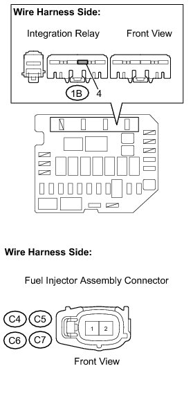
(a) Disconnect the fuel injector assembly connectors.
(b) Remove the integration relay from the engine room relay block.
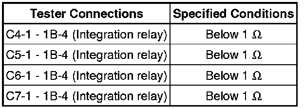
(c) Measure the resistance according to the value(s) in the table below.
Standard resistance (Check for open):
Standard resistance (Check for short):
(d) Reconnect the fuel injector assembly connectors.
(e) Reinstall the integration relay.
NG -- REPAIR OR REPLACE HARNESS OR CONNECTOR
OK -- REPAIR OR REPLACE ECM POWER SOURCE CIRCUIT ECM Power Source Circuit