How to Troubleshoot Circuits at the PCM
How to Troubleshoot Circuits at the PCMSpecial Tools Required
- Digital multimeter KS-AHM-32-003 (1) or a commercially available digital multimeter
- Pin probe (male) 07ZAJ-RDJA110 (two required)
- Flat spade probe (male) 07ZAJ-RDJA120
1. With the ignition switch ON (II), connect the HDS to the DLC, and into any of the live data screens.
2. Turn the ignition switch OFF.
3. Turn off the HDS and then turn it back ON. Go to the SCS mode and follow the screens to ground the DLC.
NOTE: Steps 1 thru 3 must be done to protect the PCM from damage, or wait at least 60 minutes before disconnecting PCM connectors.
4. Disconnect PCM connectors and probe the connector terminals from the terminal side of the connector. Make sure the connector terminal diameter, and select the suitable pin probe (male) and/or flat spade probe (male).
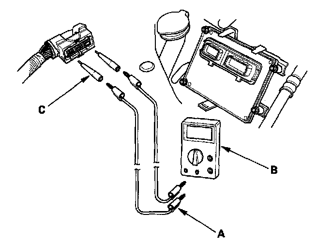
5. Connect the patch cord terminals (A) to the digital multimeter (B), and connect the other terminals of the patch cords to the pin probe (male) (C) and/or flat spade probe (male) (C).
6. Gently slide the probe into the connector terminals from the terminals side. Do not force the tips into the terminals.