Relay Box: Testing and Inspection
Relay Circuit Board Test
The relay circuit board is part of the under-hood fuse/relay box, and it contains these relays:
- A/C condenser fan relay
- Fan control relay
- Radiator fan relay
- Wiper motor relay
- Wiper intermittent relay
- Wiper high/low relay
1. Do the battery terminal disconnection procedure Procedures.
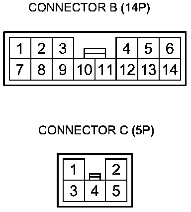
2. Disconnect under-hood fuse/relay box connectors B (14P) and C (5P).
3. Test each relay circuit as shown:
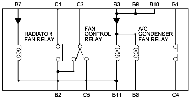
A/C condenser fan relay:
There should be continuity between terminals B1 and C4 when battery power is connected to terminal B3 (B9, or B10), and battery ground is connected to terminal B8. There should be no continuity between terminals B1 and C4 when power is disconnected.
Fan control relay:
There should be continuity between terminals C3 and C5 when battery power is connected to terminal B3 (B9, or B10), and battery ground is connected to terminal B11. There should be continuity between terminals C3 and B2 when power is disconnected.
Radiator fan relay:
There should be continuity between terminals C1 and B2 when battery power is connected to terminal B7, and battery ground is connected to terminal B11. There should be no continuity between terminals C1 and B2 when power is disconnected.
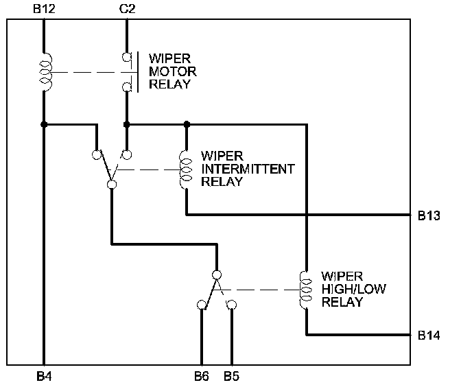
Wiper motor relay:
There should be continuity between terminals C2 and B14, and terminals C2 and B13 when battery power is connected to terminal B12, and battery ground is connected to terminal B4. There should be no continuity between terminals C2 and B14, and terminals C2 and B13 when power is disconnected.
Wiper intermittent relay:
There should be battery voltage at terminal B6 when battery power is connected to terminals C2 and B12, and battery ground is connected to terminals B4 and B13. There should be no voltage at terminal B6 when terminal B13 is disconnected.
Wiper high/low relay:
There should be battery voltage at terminal B5 when battery power is connected to terminals C2 and B12, and battery ground is connected to terminals B4,B13, and B14. There should be no voltage at terminal B5 when terminal B14 is disconnected.
4. If any of these relay circuits fail the test, replace the relay circuit board.
5. Reinstall all removed parts.
6. Do the battery terminal reconnection procedure Procedures.
A/C condenser fan relay, Fan control relay, Radiator fan relay
Wiper motor relay, Wiper intermittent relay, Wiper high/low relay