Entry Lights Control System (MICU, Rear MICU, and Drivers MPCS Unit) Input Test
Entry Lights Control System (MICU, Rear MICU, and Driver's MPCS Unit) Input Test
NOTE: Before testing the entry lights control system, troubleshoot the multiplex integrated control unit first, using B-CAN System Diagnosis Test Mode A Troubleshooting - B-CAN System Diagnosis Test Mode A.
Under-dash Fuse/Relay Box
1. Turn the ignition switch to LOCK (0) and remove the left kick panel Service and Repair.
2. Disconnect under-dash fuse/relay box connectors E, F, H, P, Q, and W.
NOTE: All connector views are wire side of female terminals.
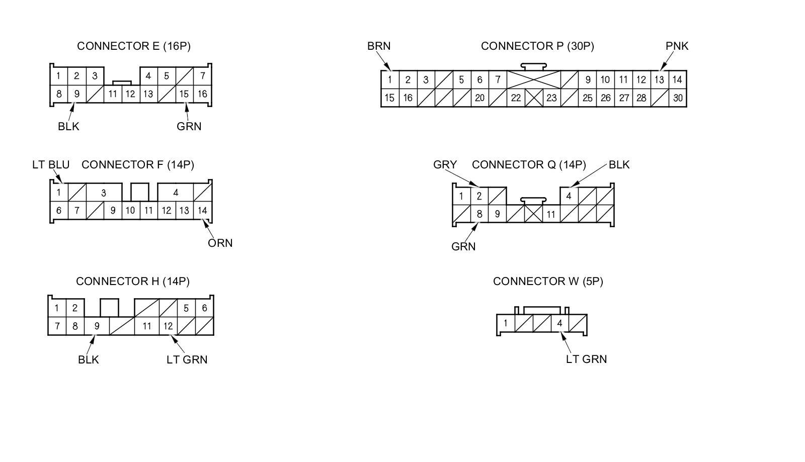
3. Inspect the connector and socket terminals to be sure they are all making good contact.
- If the terminals are bent, loose, or corroded, repair them as necessary, and recheck the system.
- If the terminals look OK, go to step 4.
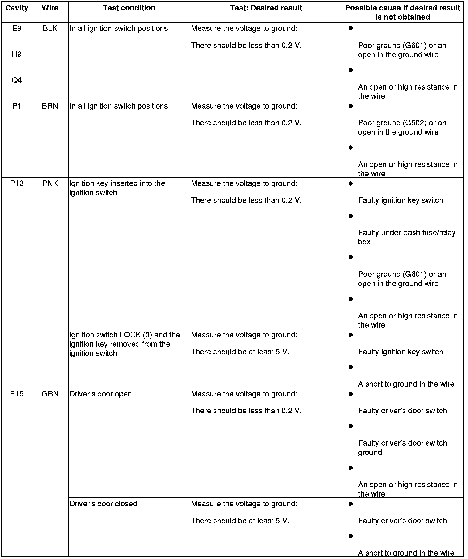
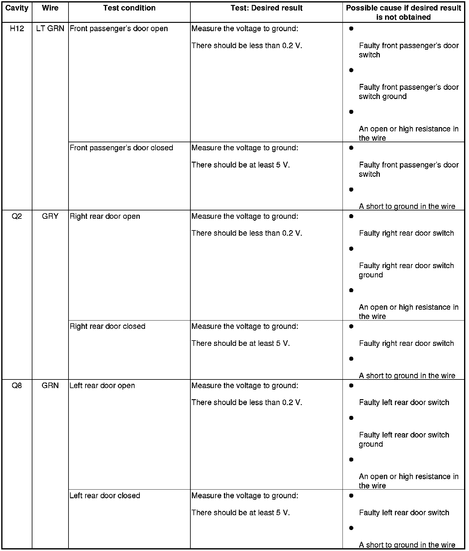
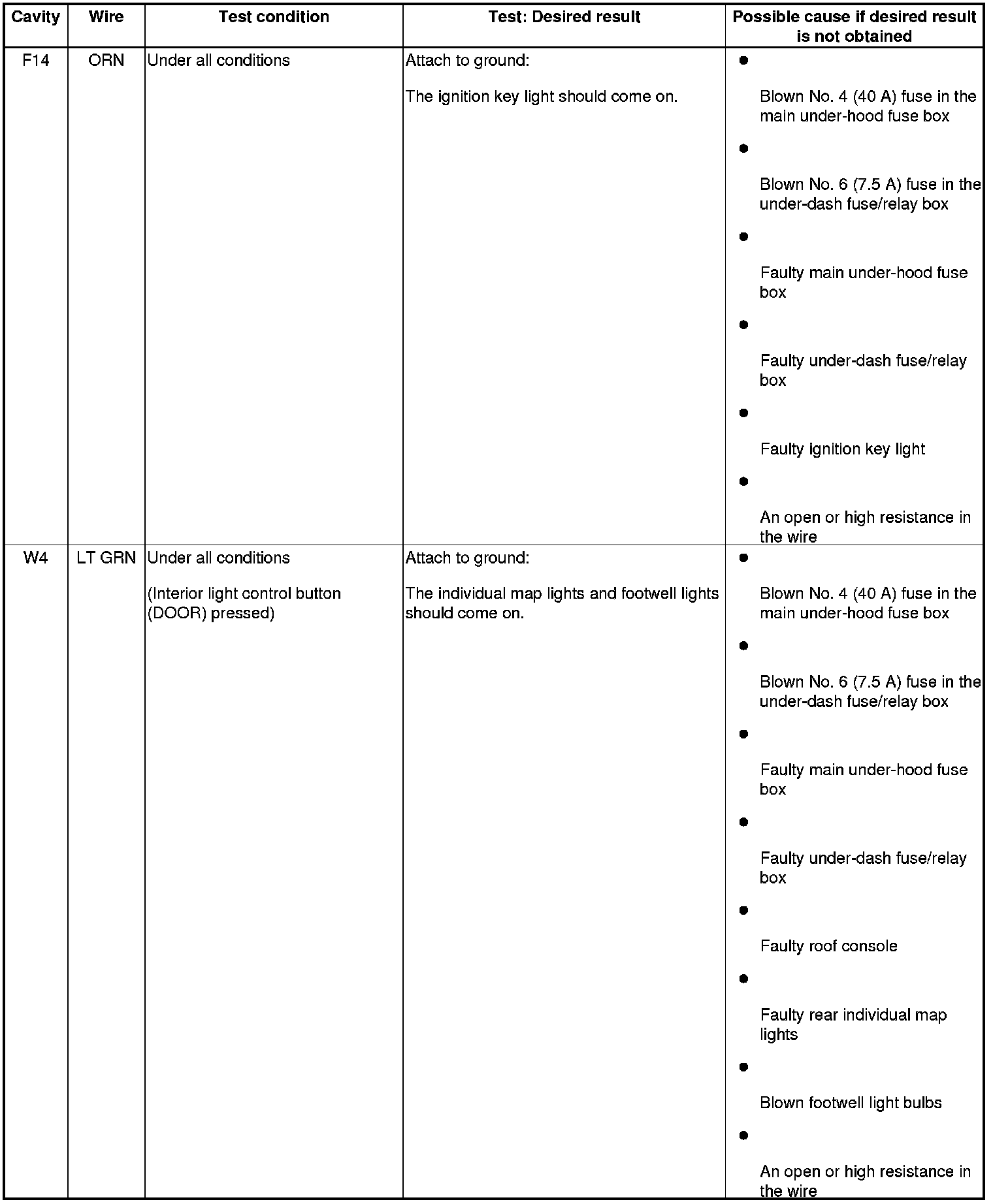
4. Reconnect the connectors, turn the ignition switch to ON (II), and do the following input tests:
- If any test indicates a problem, find and correct the cause, then recheck the system.
- If all the input tests prove OK, go to step 5.
Rear Fuse/Relay Box
5. Turn the ignition switch to LOCK (0).
6. Remove the left rear side trim Interior Trim Removal/Installation - Rear Side Area.
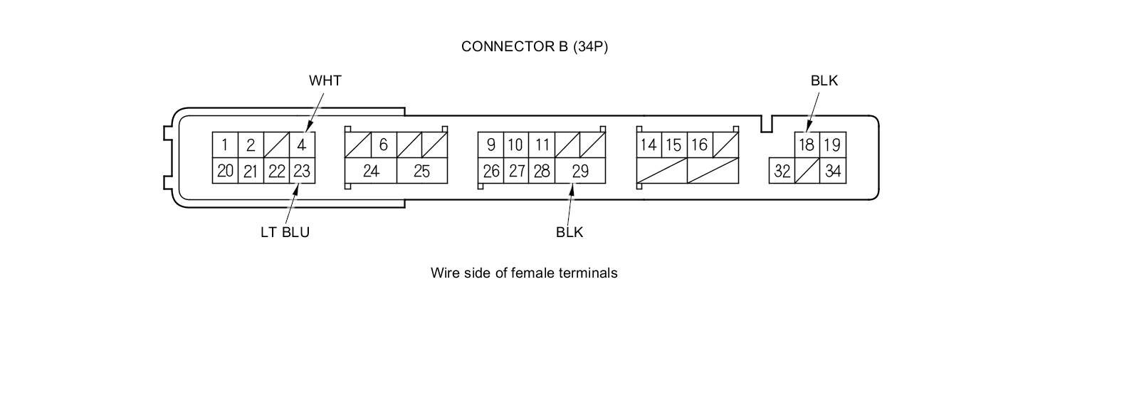
7. Disconnect rear fuse/relay box connector B (34P).
8. Inspect the connector and socket terminals to be sure they are all making good contact.
- If the terminals are bent, loose, or corroded, repair them as necessary, and recheck the system.
- If the terminals look OK, go to step 9.
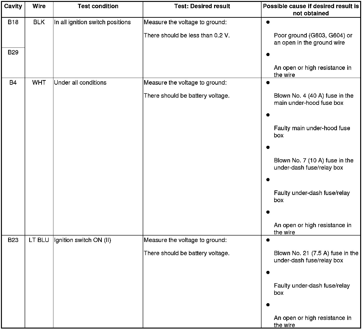
9. Reconnect the connectors, then turn the ignition switch to ON (II), and do the following input tests:
- If any test indicates a problem, find and correct the cause, then recheck the system.
- If all the input tests prove OK, go to step 10.
Driver's MPCS Unit
10. Turn the ignition switch to LOCK (0).
11. Remove the driver's door panel Front Door Panel Removal/Installation.
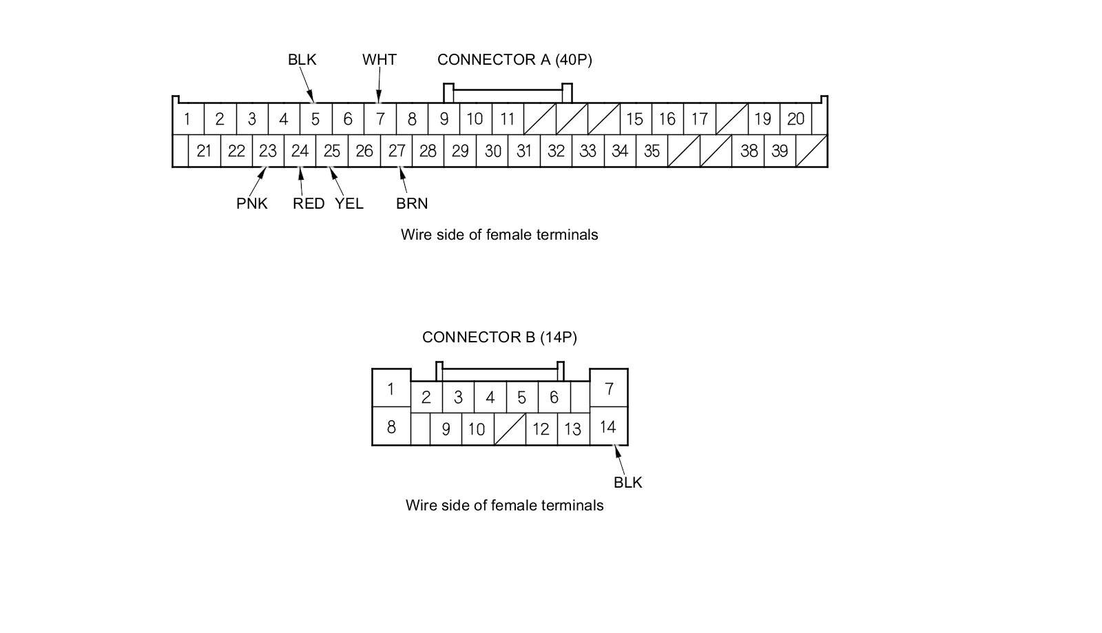
12. Disconnect driver's MPCS unit connectors A (40P) and B (14P).
13. Inspect the connector and socket terminals to be sure they are all making good contact.
- If the terminals are bent, loose, or corroded, repair them as necessary, and recheck the system.
- If the terminals look OK, go to step 14.
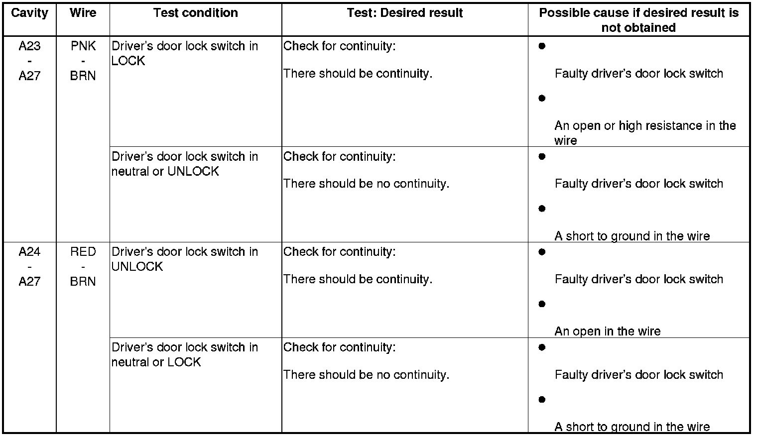
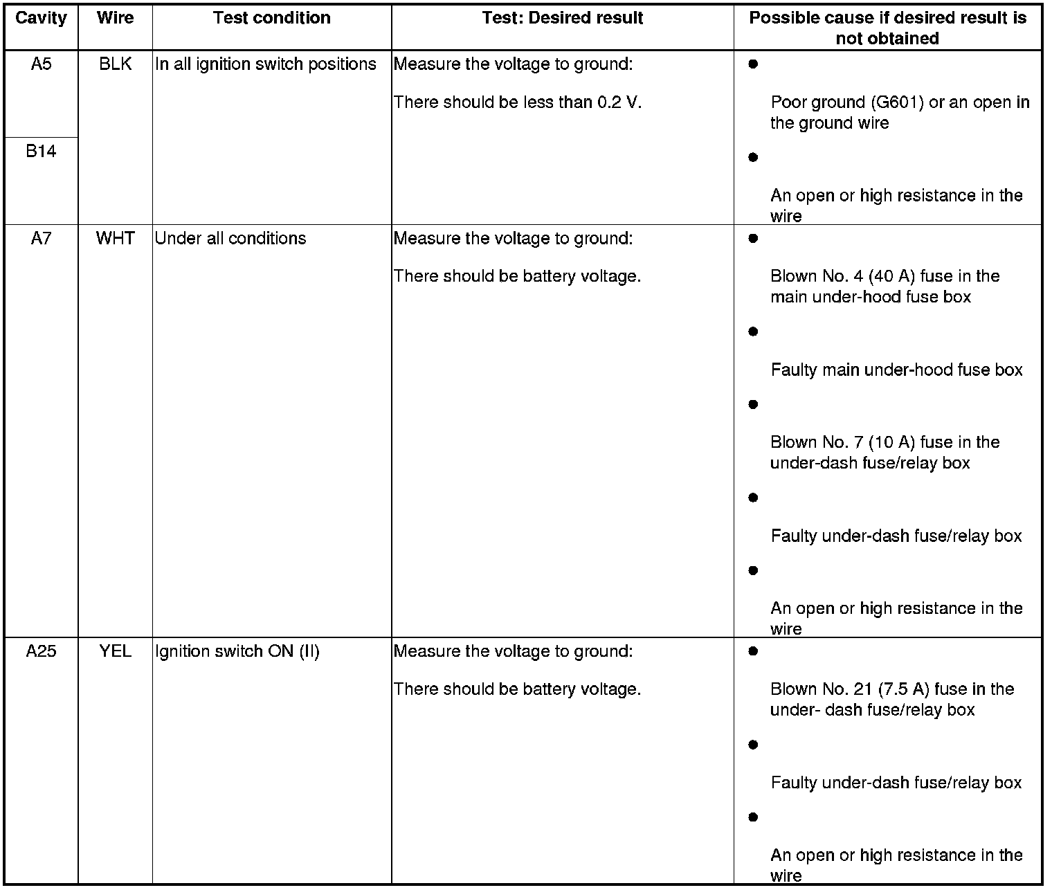
14. With the connectors still disconnected, do the following input tests:
- If any test indicates a problem, find and correct the cause, then recheck the system.
- If all the input tests prove OK, go to step 15.
15. Reconnect the connectors, and do the following input tests:
- If any test indicates a problem, find and correct the cause, then recheck the system.
- If all the input tests prove OK, go to step 16.
16. If multiple failures are found on more than one control unit, replace the under-dash fuse/relay box (includes the MICU) Under-Dash Fuse/Relay Box Removal and Installation. If input failures are related to a particular control unit, replace the control unit.