Ignition Coils, Checking
NOTE:
- Check wiring between power output stage and ignition coils, and between the ignition coils and the connector set in the connector bracket, for insulation damage.
- Component locations, Refer to "Component Overview - I " Locations
Checking secondary resistance
- Disconnect ignition wires from the ignition coils.
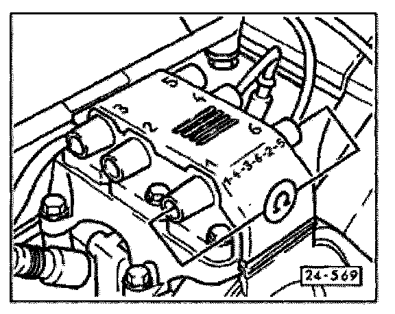
- Switch Fluke 83 multimeter to resistance range and connect between the two posts of the ignition coil being tested.
Specified value: 9000 - 14000 ohm
If the specified resistance is not obtained for any one coil:
- Replace ignition coil.
Checking primary resistance
- Disconnect power output stage harness connector. Refer to "Component Overview - I " Locations
- Check connectors for loose, corroded terminals or terminals that have been pushed out of their connector housing, and repair as necessary.
NOTE: The connector sequence in the connector bracket is immaterial because all three B+ terminals route to the ignition coils.
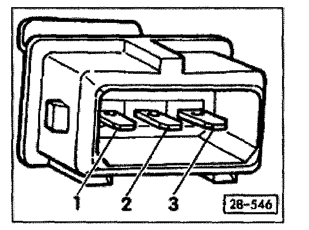
- Connect one multimeter test leads between ignition coil connector terminal in connector bracket
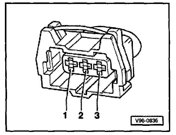
... and 3-pin power output stage connector (for each coil).
Specified value: max. 5.0 ohm
If the specified resistance is not obtained for any coil:
- Replace ignition coil.
Checking voltage supply
- Fuse for ignition coils OK
- Disconnect white connector on connector bracket.
- Switch ignition on.
- Switch Fluke 83 multimeter to voltage range and connect in sequence between Ground (GND) and all three terminals of the connector.
- Specified value: approx. battery voltage
If the specified values are not obtained:
- Check for open circuit using wiring diagram, repair as necessary, also check fuses.