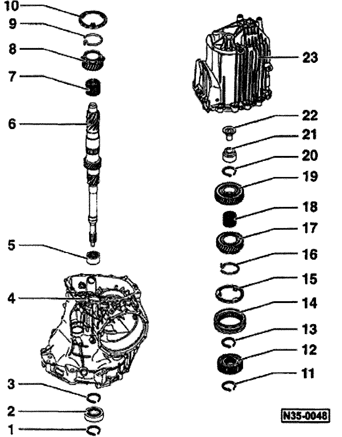
Input Shaft, Disassembling & Assembling: Overview
Special tools and equipment
- VW222A pilot drift
- VW295 needle-bearing drift
- VW295A needle-bearing drift
- VW401 thrust plate and VW402 thrust plate
- VW407 punch and VW408A punch
- VW415A tube and VW416B tube
- VW4471 thrust pad
- VW771 slide hammer, complete set
- 30-24 drift
- 30-100 press tube
- 40-105 thrust piece
- 40-202 press-out piece
- Kukko 17/2 separating tool
- 21/4 KUKKO extractor
Notes:
- When installing the input shaft or new gears, consult technics/data, Application and ID
- By replacing items -2-, -4- and/or -6-, the position of the ball bearing is influenced. In this case, the input shaft must be readjusted, Input Shaft, Adjusting
1. Circlip
- Identification
- Installed position Fig. 15 Allocation of Circlips item 1.
2. Input shaft ball bearing
3. Circlip
- Identification
- Installed position Fig. 15 Allocation of Circlips item 2.
4. Transmission - housing
5. Needle bearing
- Secured with bolt, Fig. 1 Securing Bolt For Needle Bearing
- Driving out, Fig. 2 Driving Out Needle Bearing
- Allocation of input shaft/needle bearing, Fig. 3 Allocation of Input Shaft/Needle Bearing
- Installed position, Fig. 4 Allocation of Needle Bearing
- Pressing in, Fig. 5 Pressing In Needle Bearing
- Securing, Fig. 6 Installing Securing Bolt (Arrow)
6. Input shaft
- With oiling sleeve
- Driving In oiling sleeve, Fig. 7 Driving In Oiling Sleeve Into Input Shaft
- Allocation of input shaft/needle bearing, Fig. 3 Allocation of Input Shaft/Needle Bearing
7. Needle bearing for 3rd gear
- Identification
8. 3rd gear
9. Spring
- Inserting in 3rd gear, Fig. 13 Inserting Spring Into Gear
- Allocation of spring to gear, Refer to parts supplier.
10. Synchronizer - ring for 3rd gear
- Checking for wear, Fig. 14 Checking Synchronizer Ring For Wear
11. Circlip
- Identification
- Installed position, Fig. 15 Allocation of Circlips, item 3.
12. Synchronizer - hub for 3rd and 4th gears
- Shoulder faces third gear
- Pressing off, Fig. 12 Pressing Off Synchronizer Hub For 3RD and 4TH Gears
- Pressing on, Fig. 17 Pressing on Synchronizer Hub For 3RD and 4TH Gears
13. Circlip
- Identification
- Installed position, Fig. 15 Allocation of Circlips, item 4.
- Redetermining thickness when replacing synchronizer body, Fig. 16 Determining Thickness of Circlip
14. Operating sleeve for 3rd and 4th gears
- Installed position, Fig. 18 Installation Position of Operating Sleeve
15. Synchronizer - ring for 4th gear
- Checking for wear, Fig. 14 Checking Synchronizer Ring For Wear
16. Spring
- Inserting in 4th gear, Fig. 13 Inserting Spring Into Gear
- Allocation of spring to gear, Refer to parts supplier.
17. 4th gear
18. Needle bearing for 4th gear
- Identification
19. 5th gear
- Pressing off, Fig. 11 Pressing Off 5TH Gear
- Pressing on, Fig. 19 Pressing on 5TH Gear
20. Circlip
- Identification
- Installed position, Fig. 15 Allocation of Circlips, item 5.
- If 5th gear IS replaced, redetermine thickness of circlip, Fig. 16 Determining Thickness of Circlip
21. Roller sleeve
- Always replace
- Damaged when removed
- Pulling out, Fig. 8 Pulling Out Roller Sleeve
- Installed position, Fig. 9 Installed Position of Roller Sleeve
- Driving in, Fig. 10 Driving In Roller Sleeve
22. Plastic sleeve
- Made of plastic
23. Transmission - cover
- Coat sealing surfaces with a thin layer of sealant AMV 188 001 02