Ignition Power Stage: Testing and Inspection
Checking actuation
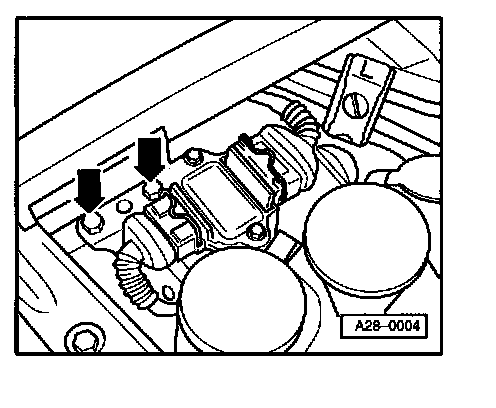
- Remove bracket along with ignition coil power output stages -N122- and -N192- (arrows).
- Disconnect all fuel injector harness connectors and hold-downs.
- Disconnect 5-pin connectors (from ECM) from both power output stages.
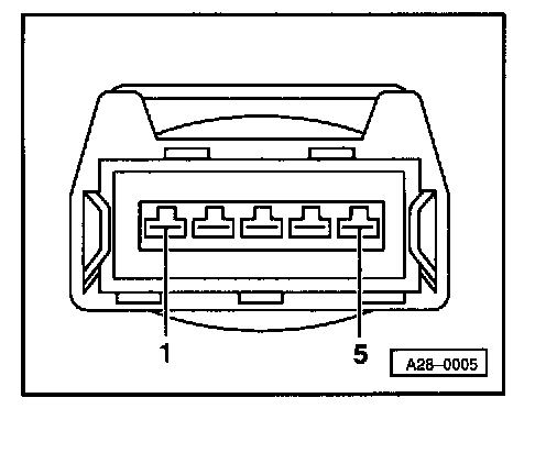
- Connect one lead of VAG 1527B LED voltage tester to engine Ground. Connect other lead in sequence to check for voltage at terminals 1, 2, 4 and 5 of each 5-pin connector.
For each test (at each connector terminal):
- Briefly operate starter motor.
LED must flash each time.
If LED does not flash:
- Connect VAG 1598/19 test box to Engine Control Module (ECM) harness connector. Testing and Inspection
- Check wiring for open circuit, short to B+ or short to Ground between power output stage harness connector and ECM. See Electrical Wiring Diagrams, Troubleshooting and Component Locations.

Power output stage 5-pin VAG 1598/19 test box socket
connector terminal (ECM terminal)
Black (-N 122-)
1 B8
2 B7
4 B6
5 B5
Brown (-N192-)
1 B14
2 B13
4 B15
5 B16
If wiring between power output stage and ECM is OK:
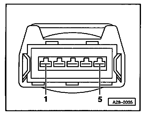
- Check wiring (Ground connection) for continuity between terminal 3 of each 5-pin connector and engine Ground.
If wiring and connections are OK:
- Replace ECM and generate new readiness code. Testing and Inspection
Checking power output stage function
- Both 5-pin connectors remain connected.
- Disconnect both 4-pin harness connectors from ignition coil power output stages.
- Connect VAG 1527B LED voltage tester between B+ (e.g. one ignition coil terminal 15) and one terminal at 4-pin power output stage connector.
NOTE: LED tester will light dimly to indicate very low voltage while the engine is not running, then become brighter (flashing) during engine cranking.
For each test (at each connector terminal):
- Briefly operate starter motor.
LED must flash.
If LED does not flash at one or more terminals:
- Replace power output stage.
- Check readiness code. If Diagnostic Trouble Code (DTC) memory has been erased, then generate new readiness code. Testing and Inspection