Cruise Control System (CCS), Checking
Cruise Control System (CCS), Checking
With the exception of the operating switch, there are no components specific to the cruise control system; all functions are implemented by the engine control module.
Work sequence
WARNING: To avoid risk of accident when performing measurement and test drives, pay attention to safety precautions.
- Connect vehicle diagnostic, testing and information system VAS 5051 and select vehicle system "01 - Engine electronics" from list. Ignition must be on. Connecting VAS 5051 Scan Tool
Indicated on VAS 5051:
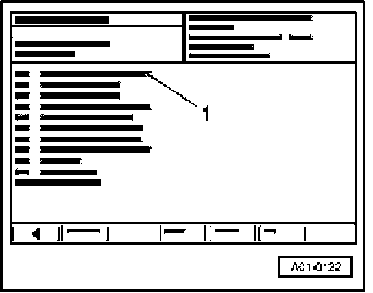
- From list -1- select diagnostic function "08 - Reading measured value block".
Indicated on VAS 5051:
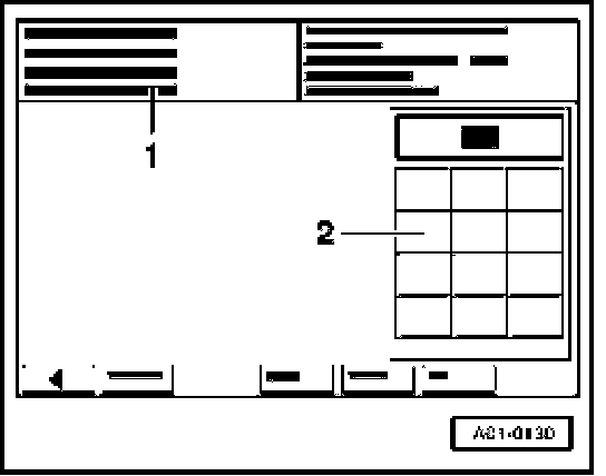
1 Enter display group
- Use keypad -2- to enter "066" for "Display group number 066" and confirm by touching Q key.
Indicated on VAS 5051:
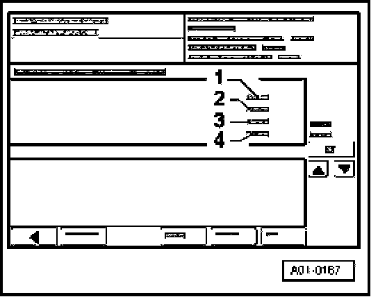
- Check display in zone -2-.
- Perform test drive to establish whether or not switch positions are shown in display zone -4-.
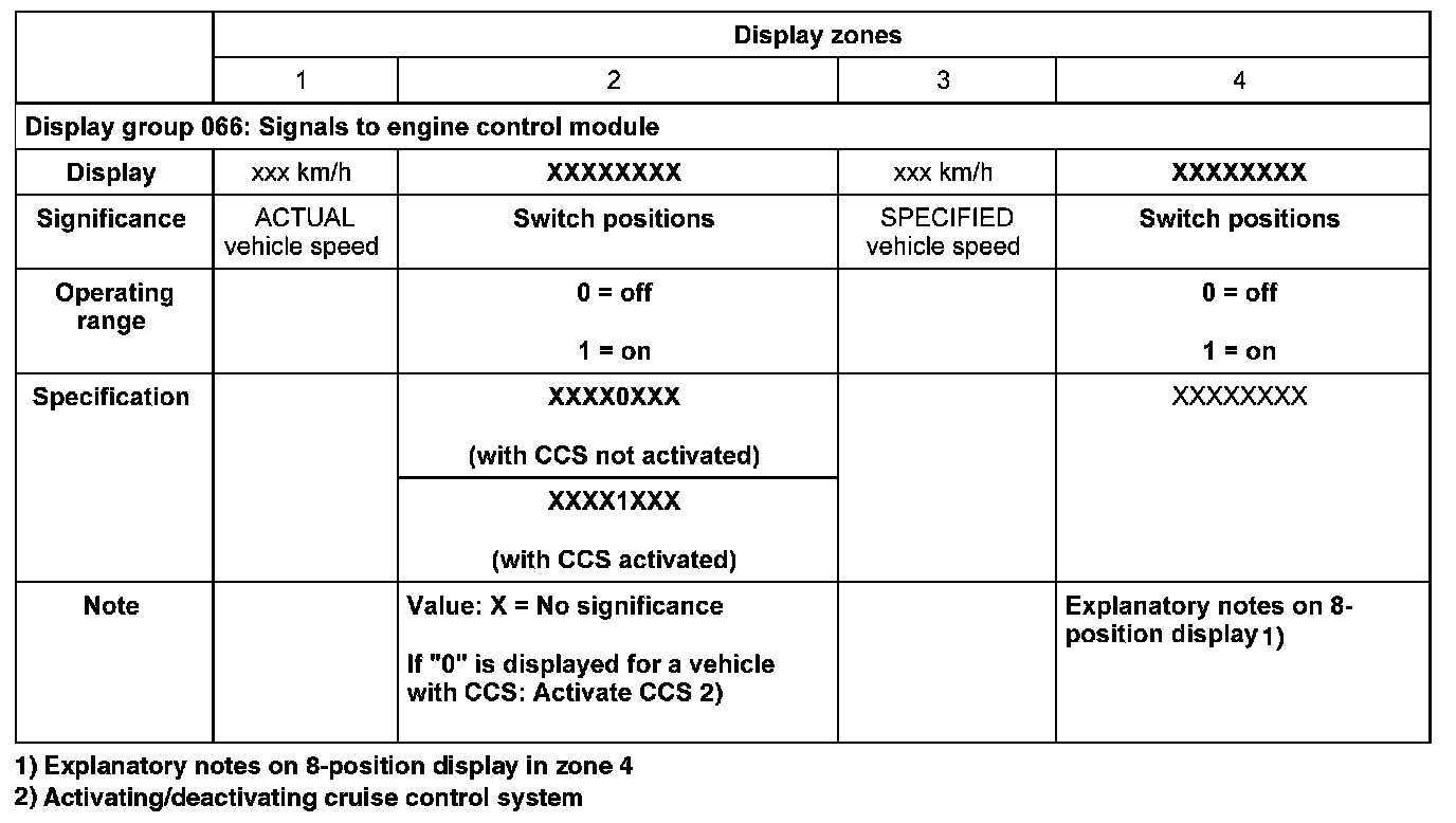
Display Group 066:
- Terminate function "08 - Reading measured value block" by touching <- key.
If "0" appears in display zone 2 even with CCS activated:
- Connect test box V.A.G 1598/31 at wiring harness to engine control module. Actual engine control module is also to be connected. Wiring And Component Check Using Test Box V.A.G 1598/31
- Connect multimeter for voltage measurement as follows.
Test box V.A.G 1598/31 Measure to
Socket
38 Engine Ground
- Switch on ignition.
- Specification with CCS deactivated: 0 V
- Specification with CCS activated: approx. battery voltage
If readings do not match specifications:
- Check for open circuit and short to Ground/positive in following wiring:
Test box V.A.G Cruise control switch -E45-
1598/31 Socket
38 -
- Eliminate open circuit in wiring/short circuit if necessary.
Explanatory notes on 8-position display in zone 4
Switch position Display zone 4
CCS latched "OFF" 0 X 0 0 0 0 0 0
CCS latched "ON" (standby) 1 X 0 0 0 0 0 1
CCS non-latched "OFF" 1 X 0 0 0 0 1 1
Tip down/deceleration 1 X 0 0 0 1 0 1
Tip up/acceleration 1 X 0 0 1 0 0 1
Set 1 X 0 1 0 0 0 1
Reactivation 1 X 1 0 0 0 0 1
If readings do not match specifications in display zone 4:
- Check Cruise control switch -E45-.