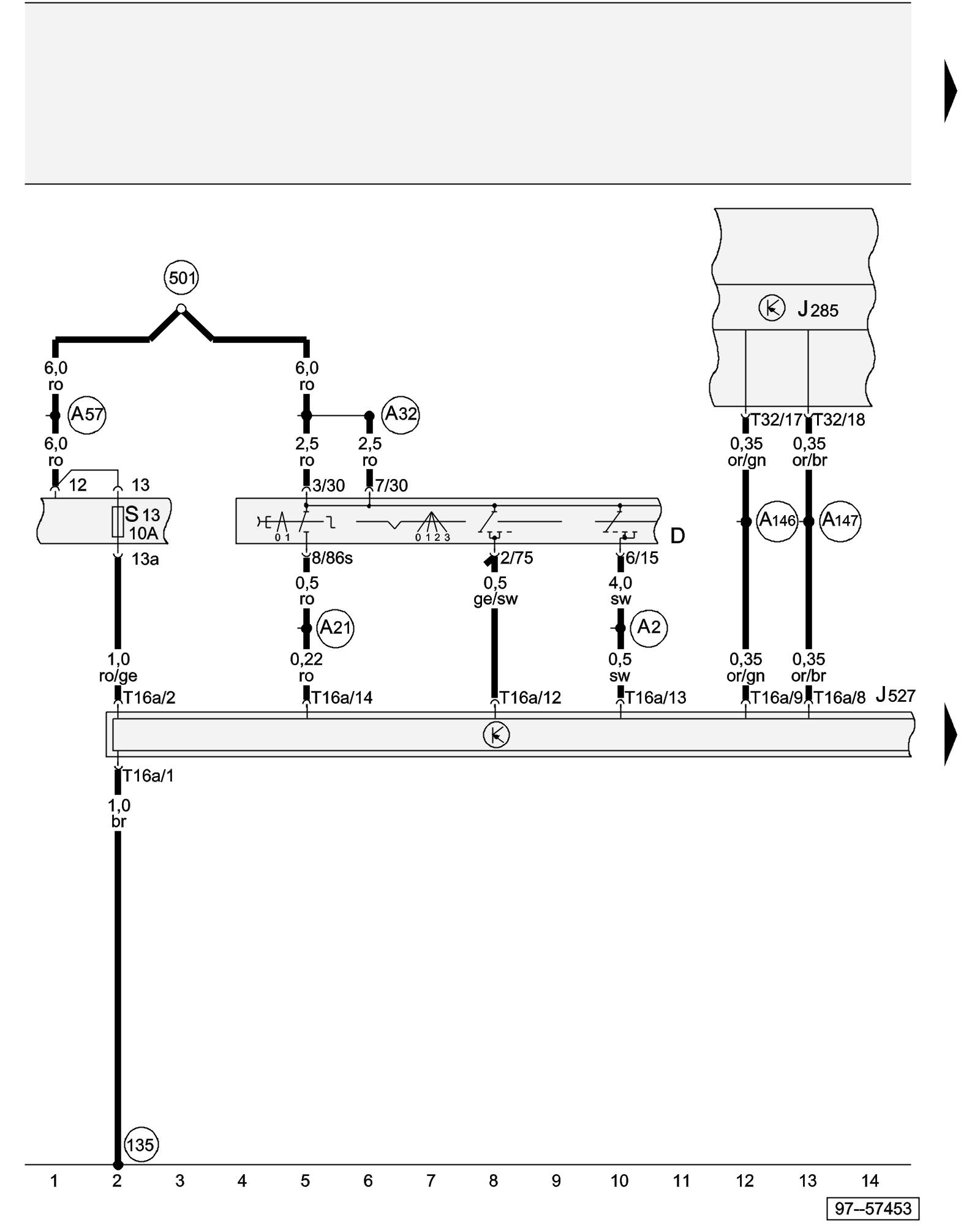
Diagram 321/2 (Tracks 1-14)
IMPORTANT NOTE:
This manufacturer uses "Track" style wiring diagrams.
For information on how to use these diagrams effectively, please refer to Diagram Information and Instructions. Diagram Information and Instructions
Steering Column Electronic Systems Control Module, Fuse, Control module with indicator unit in instrument panel insert, Ignition/Starter Switch
ws = white
sw = black
ro = red
br = brown
gn = green
bl = blue
gr = grey
li = lilac
ge = yellow
or = orange
rs = pink
D - Ignition/Starter Switch
J285 - Control module with indicator unit in instrument panel insert
J527 - Steering Column Electronic Systems Control Module
S13 - Fuse in fuse holder/relay panel
T16a - 16-Pin Connector, black, on steering Column Electronic Systems Control Module
T32 - 32-Pin Connector, blue, on instrument panel insert
(135) - Ground connection -2-, in instrument panel wiring harness
(501) - Threaded connection -2- (30), on the relay plate
(A2) - Plus connection (15), in instrument panel wiring harness
(A21) - Wire connection (86s), in instrument panel wiring harness
(A32) - Plus connection (30), in instrument panel wiring harness
(A57) - Plus connection -3- (30), in instrument panel wiring harness
(A146) - Comfort System High-bus Connection (in instrument panel wiring harness)
(A147) - Comfort System Low-bus Connection (in instrument panel wiring harness)
Next Diagram 321/3 (Tracks 15-28)