Data Bus On Board Diagnostic Interface -J533-, Removing and Installing
Data Bus On Board Diagnostic Interface -J533-, Removing And Installing
Required tools and special equipment
- Protective cap for fiber optic cable, Part No.4E0 972 401
Removing
- To replace the control module, select the "Replace" function for the respective control module in "Guided Fault Finding".
- VAS 5051 Vehicle Diagnostic, Testing and Information System must be used for this purpose.
WARNING: When working on knee airbag, observe safety precautions for working on airbags.
CAUTION:
- Switch off all electrical consumers.
- Switch ignition off and remove ignition key.
- Remove glove compartment:
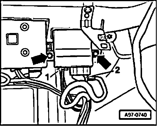
- Remove bolts -arrows-.
- Remove control module.
- Disconnect electrical connector -2-.
- Disconnect harness connector -1- for fiber optic cable.
NOTE: The glove compartment bracket is shown removed in the illustration.
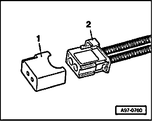
- Seal the open wiring set connector -2- of fiber optic cable with protective cap -1- Part No. 4E0 972 401.
NOTE: The protective cap prevents soiling or mechanical damage of the abutting face of fiber optic cable, which otherwise would impair signal transmission.
Installing
Install in reverse order of removal, noting the following.
Tightening torque
Component Nm
Control module to chassis 4