System Diagram
Power steering pump, reservoir and hydraulic lines, overview (vehicles with 6-cyl. engine)
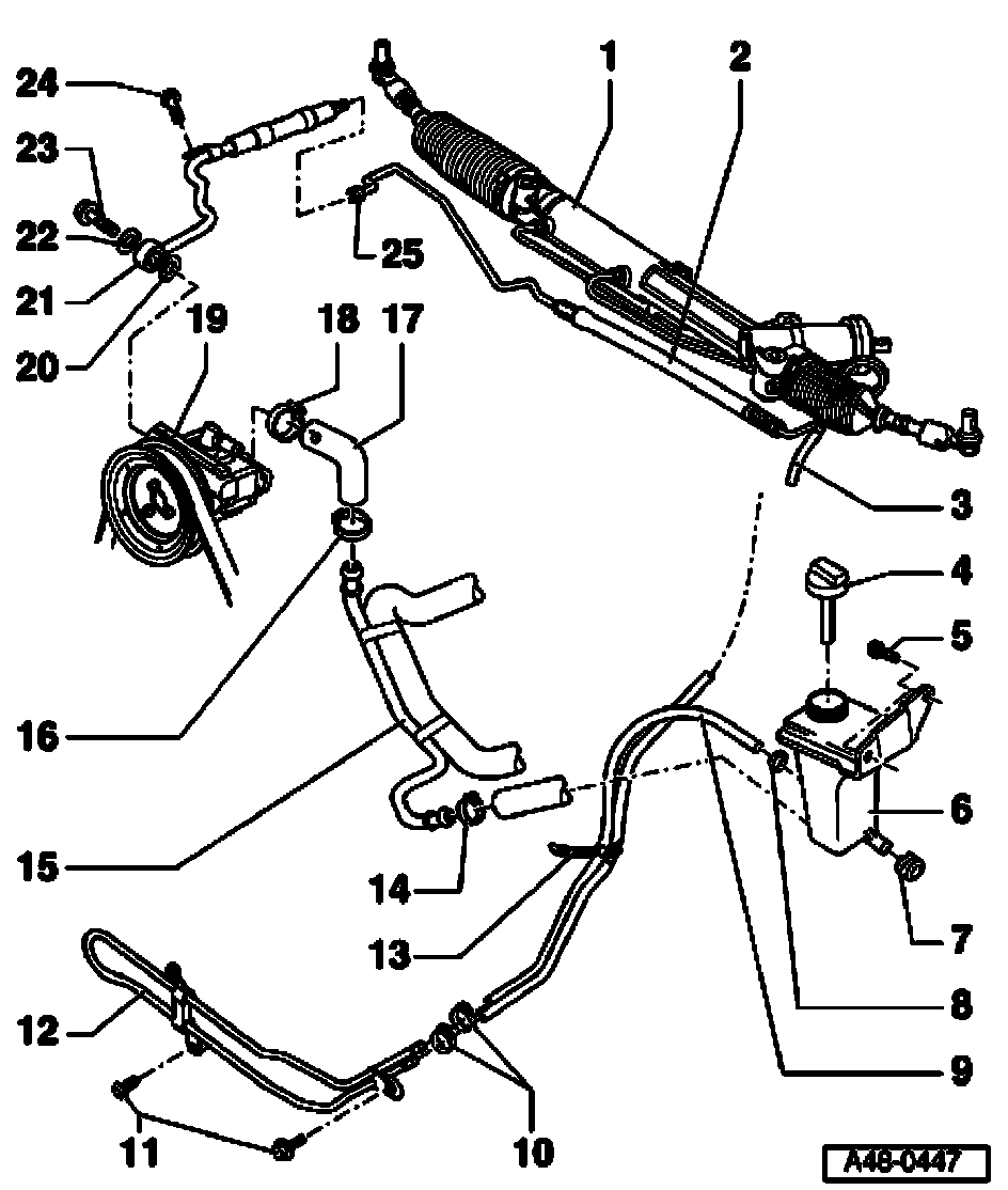
1 - Power steering gear
2 - Expansion hose
3 - Return hose
4 - Cap with dipstick
^ Check fluid level
5 - Hex bolt, 5 Nm
6 - Reservoir
^ Re-fill with hydraulic fluid, Part No. G 002 000
7 - Rubber bushing
8 - Clamp
^ Use V.A.G 1275 to tighten
^ Always replace
9 - Return hose
^ Between reservoir and cooling line
10 - Clamp
^ Use V.A.G 1275 to tighten
^ Always replace
11 - Hex bolt, 10 Nm
12 - Cooling line
13 - Cable tie
14 - Hose clip
^ Use V.A.G 1275 to tighten
^ Always replace
15 - Intake hose
^ Installation position
16 - Clamp
^ Use V.A.G 1275 to tighten
^ Always replace
17 - Intake hose
^ Installation position
18 - Clamp
^ Use V.A.G 1275 to tighten
^ Always replace
19 - Power steering pump
^ For 6-cyl. gasoline engines
^ For correct version see Parts catalog
^ Fill with fluid before installing [] Note Power steering pump, reservoir and hydraulic lines, assembly overview
20 - Oil seal
^ Always replace
21 - Pressure hose
22 - Seal
^ Always replace
23 - Banjo bolt, 50 Nm
24 - Hex bolt, 8 Nm
25 - Pressure hose connection, 40 Nm