Fuel Level Sensor (G)
Fuel Level Sensor (G)
Special tools, testers and auxiliary items required
• (T10202)
Removing
Follow all safety precautions. Refer to => [ Safety Precautions ] General Information.
Follow the guidelines for cleanliness. Refer to => [ Clean Working Conditions ] Clean Working Conditions.
- Position driver's seat as far back and up as possible using the full seat adjustment range.
Risk of destroying electronic components when disconnecting the battery.
• Observe measures for disconnecting battery.
- Disconnect the battery.
Danger of fuel entering vehicle interior.
• To remove fuel level sensor, fuel tank must be empty.
- Empty fuel tank. Refer to => [ Fuel Tank, Draining ] Procedures.
- Remove the right seat frame in 2nd row.
Risk of injury.
• Wear safety gloves.
- Cut the floor covering along the perforation - arrows - on the right side with a carpet knife - 1 -.
- Fold the floor covering to the side - arrow -.

- Remove nuts - 1 to 4 - and remove right locking flange cover.
- Disconnect electrical harness connector - 3 - at right locking flange.

Risk of injury from fuel.
• To reduce residual pressure remaining in fuel system, lay a clean cloth around the connector and carefully loosen connector.
- Disconnect the fuel supply line - 2 - from right locking flange.
- Remove locking ring with (T10202).

- Pull the right locking flange with seal out of the fuel tank a bit.

- Disconnect electrical connectors - 1 and 2 - on the underside of the right locking flange.
- Disconnect fuel line - arrow - by pressing release button.

- Lay aside right locking flange with auxiliary heater intake lines connected.
• Ignore - 1 to 4 -.
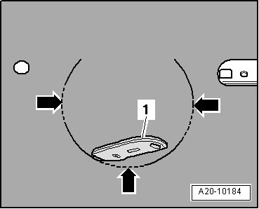
- Grasp in fuel tank opening and remove fuel level sensor through guide - arrow 2 - while pressing locking tab - arrow 1 -.

• Fuel level sensor is shown without fuel tank to provide a better illustration.
Installing
• Tightening specification, refer to => [ Fuel Delivery Unit and Fuel Level Sensor (G) Overview ] Fuel Delivery Unit and Fuel Level Sensor (G) Overview.
Install in reverse order, paying attention to the following:
• Replace seal.
- Insert fuel level sensor into guide until it engages audibly.
- Connect electrical connectors - 1 and 2 - on the underside of right locking flange.
- Install the new locking flange seal dry.
- Bring the right locking flange into the installation position.
• Tab - 2 - on the right locking flange faces toward arrow marking and must lie between tabs - 1 and 2 - on fuel tank.

- Install locking flange cover.
- Install the frame into the floor covering. and to the Electronic Parts Catalog (ETKA)
- Install right seat frame in 2nd row.
- Be sure to follow the procedure for connecting the battery and afterwards.