Part 1
Engine, Removing
• With lock carrier removed, engine is removed downward with transmission and subframe.
Special tools, testers and auxiliary items required
• Old oil collecting and extracting device (V.A.G 1782 )
• Hose clamp pliers (V.A.G 1921)
• Spark plug connector pliers (V.A.G 1922)
• Step ladder (VAS 5085)
• Scissor lift platform (VAS 6131 A) with support set for Audi (VAS 6131/10)
• Drip tray for workshop crane (VAS 6208)
• Ring screw (3368)
• Tension strap (T10038)
• If engine and transmission are to be separated after removal, the Supplementary Set (VAS 6131/11) will also be required.
Procedure
• Drained coolant must be stored in a clean container for disposal or reuse.
• All cable ties opened or cut during engine removal must be reinstalled at the same locations during installation.
- Remove plenum chamber cover rubber seal.
- Remove plenum chamber cover - 1 - toward front - arrows -.

CAUTION!
Observe procedures when connecting battery.
- With ignition switched off, disconnect Battery Ground (GND) cable - arrow -.

- Discharge refrigerant circuit.
- Extract hydraulic oil for power-steering from reservoir using old oil collecting and extracting device (V.A.G 1782).
CAUTION!
Cover cap of expansion tank with rag and open carefully, as hot steam i.e. hot coolant may escape when opening.
- Open cap of coolant expansion tank.
- Remove both front wheels.
- Remove quick-release fasteners - 1 -, remove screws - 2 - and remove noise insulation.

- Remove bracket for noise insulation - arrows -.

- Remove left and right front wheel housing liners.
- Remove front bumper cover.
- Remove left air guide - arrow - in front of auxiliary cooler.

- Remove right air guide - arrow - in front of auxiliary cooler.

- Place drip tray for workshop crane (VAS 6208) under engine.

- Remove drain plug - arrow - on coolant thermostat housing and drain coolant from engine.
- Disconnect lower coolant hose from radiator - arrow - and drain residual coolant.

- Place old oil collecting and extracting device ( V.A.G 1782) under engine.

- Disconnect hydraulic lines to cooling coil at left rear of bumper - arrows -.
- Remove cover - 1 - in engine compartment (left side).

- Remove cover - 1 - in engine compartment (right side).

- Disengage Evaporative Emission (EVAP) Canister Purge Regulator Valve (N80) - 1 - from air guide.

- Remove bolts - arrows -.
- Remove air duct - 2 -.
- Disconnect top coolant hose - arrow - from radiator.

- Remove electrical harness connectors - 1 - and - 2 - from bracket and disconnect them.

- Free up wires to lock carrier.
- Disconnect electrical harness connector - arrow - for headlamps at both sides of the vehicle.

- Free up electrical wiring.
- Disconnect electrical harness connector - arrow - for left and right airbag sensors on lock carrier.

- Free up cables.
- Remove hood cable at lock carrier.
- Disconnect electrical harness connector - arrow - for right fan.

• To prevent damage to condenser and also to the refrigerant lines/hoses, ensure that the pipes and hoses are not stretched, kinked or bent.

- Remove refrigerant line - arrow - leading to A/C compressor.
- Remove refrigerant line - arrow - leading to A/C evaporator.

- Remove bolts - arrows - at left and right side of bumper.

- Pull off hood seal from lock carrier and fender edges.
- Remove bolts at impact absorbers - arrows - at left and right.

• A second technician is required to remove the lock carrier.
- Remove lock carrier and set aside so it cannot fall.
- Remove rear engine cover - arrows -.

- Remove front engine cover - arrows 1 and 2 -.

- Remove coolant hoses - 1 - and - 2 -.

- Remove coolant expansion tank - arrow -.
- Disconnect electrical wiring to Engine Coolant Level (ECL) Warning Switch (F66) at bottom of expansion tank.
- Disconnect vacuum line - arrow - to brake booster at bulkhead.

- Unclip coolant hose - arrow - from bracket on bulkhead.

- If installed, disconnect vacuum line - arrow - to vacuum reservoir.

- Disconnect vacuum hose - arrow - from intake manifold.

- Disconnect coolant hose - arrow - to heater core at rear coolant pipe on engine.

- If installed, disconnect vacuum line at area designated with - arrow -.

- If installed, disconnect electrical harness connector - arrow - for After-Run Coolant Pump (V51) (behind auxiliary cooler at left) and free up electrical wire.

• Place a rag under separating point to catch escaping hydraulic fluid.
- Disconnect hose - 1 - from power steering fluid reservoir.

• Ignore - 2 -.
- Disconnect coolant hoses at positions indicated by - arrows -.

- Disconnect coolant hoses at positions indicated by - arrows -.

- Disconnect coolant hose to oil cooler - arrow -.

- Disconnect coolant hoses at positions indicated by - arrows -.

- Remove bolts - 1 - and - 2 -.

- Remove right auxiliary cooler together with coolant hoses.
• The hose - arrow - can remain connected at auxiliary cooler.
CAUTION!
Note rules of cleanliness for working on the fuel injection system. Refer to => [ Clean Working Conditions ] Clean Working Conditions.
CAUTION!
Fuel system is under pressure! Before opening system, place clean rags around the connection. Then release pressure by carefully loosening the connection.
- Remove fuel hose from connection on fuel rail pipe. To do so, counterhold using an open-end wrench at hex head - 1 - and - 3 - and remove union nut - 2 -.

- Disconnect electrical harness connector - 2 - from Evaporative Emission (EVAP) Canister Purge Regulator Valve ( N80).

- Disconnect electrical harness connector - 3 - at Mass Air Flow (MAF) Sensor (G70).
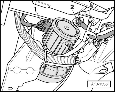
- Disconnect hose - 1 - to Secondary Air Injection pump.
- Disconnect air guide hose - 4 - at Mass Air Flow sensor.
- Move wiring harness clear at air filter housing.
- Remove clip - arrow - and remove air filter housing with Mass Air Flow sensor.
- Disconnect air hose - arrow - at right on engine.

- Remove bracket for electrical harness connectors - 1 to 4 - at right from bulkhead.

- Remove nut - 1 - and remove fuse strip on plus wire terminal clamp.

- Disconnect positive cable - 2 - on battery positive terminal.
- Pull positive cable through bulkhead toward front.
- Free up wiring harness.
• Disregard - 3 -.
- Pry off both covers - 3 - using a screwdriver.

- Loosen hex-nuts - 4 - by several turns.
- Loosen wiper arms - 2 - from respective wiper axle by tilting slightly.
- Remove nuts completely and remove wiper arms.
CAUTION!
To prevent the cowl grille - 5 - from tearing when removing, coat transition between windshield and cowl grille with a soapy solution and pull grille up vertically out of fastening strip beginning at edge of window.
- Disconnect securing clips - 1 - and remove cowl grille - 5 -.
- Remove cover for E-Box in plenum chamber - arrows -.

- Using a screwdriver, carefully pry off mounting bracket - arrow - and remove Engine Control Module from E-Box.

• Engine Control Module remains connected at wiring harness.
- Release retaining hooks - arrows - toward outside and remove retaining bracket.

- Disconnect all electrical harness connectors on connector station - 2 - using spark plug connector pliers (V.A.G 1922 ).

- Remove electrical wire connection - 1 -.
- Disengage locking mechanisms - arrows - and remove secondary relay carrier in E-Box toward top.

- Disengage engine wiring harness at E-Box and bulkhead.
- Remove Ground (GND) connection - arrow -.

- Remove bracket for electrical harness connectors - 1 to 4 - at left from bulkhead.

- Free up wiring harness.
- Set electrical wiring harness on engine and secure Engine Control Module against falling down.
- Disconnect electrical harness connector - 1 - at Secondary Air Injection (AIR) Pump Motor (V101).
- Remove Ground (GND) cable - 2 - on longmember.
- Place old oil collecting and extracting device ( V.A.G 1782) under engine.

- Disconnect hydraulic pressure line for power-steering - arrow - at left next to oil pan.
• To prevent damage to condenser and also to the refrigerant lines/hoses, ensure that the pipes and hoses are not stretched, kinked or bent.

- Remove bolts - 1 - and - 2 -.
Part 2