Fuel Pressure Regulator and Holding Pressure, Checking
Fuel Pressure Regulator and Holding Pressure, Checking
• The fuel pressure regulator is found in the fuel filter under the tank.
Special tools, testers and auxiliary items required
• Pressure Gauge (V.A.G 1318) with Adapter (V.A.G 1318/6) and Adapter ( V.A.G 1318/7)
Test conditions
• Fuel pump relay OK
• Fuel pump OK
• Fuel filter OK
• Battery voltage at least 11 V
• Vehicles with automatic transmission: Selector lever set to P or N
Check pressure system
- Open the fuel tank lid briefly (pressure should drop).
- Remove engine cover.
CAUTION!
The fuel system is pressurized. Before loosening hose connections or opening the test connection (to measure fuel pressure), place a cloth around the connection. Then release pressure by carefully loosening the connection.
- Use cloth to cover union (subject to fuel pressure).
- Remove fuel hose from fuel rail pipe connection.. To do so, counterhold using an open-end wrench at each hex head - 1 - and - 3 - and remove union nut - 2 -.

- Unscrew pressure gauge (V.A.G 1318) with adapter (V.A.G 1318/6), adapter ( 1318/7) between supply line and fuel rail.
- Open pressure gauge cut-off valve. Lever points in direction of flow.
- Start engine and run at idling speed.
- Measure fuel pressure.
Specification: approx. 3.5 bar
- Switch ignition off.
- Test for leaks and holding pressure by watching pressure drop on gauge.
• After 10 minutes the remaining pressure should be at least 2.5 bar.
If holding pressure drops below 2.5 bar:
- Start engine and run at idling speed.
- Switch off ignition once pressure has built up. At the same time, close cut-off valve of pressure gauge (V.A.G 1318) (lever at right angle to direction of flow).

- Observe pressure drop on gauge.
Pressure drops again:
- Check pressure gauge for tightness.
- Check line and O-rings at the fuel rail and injectors for tightness.
Pressure does not drop:
- Check pressure regulator in fuel filter.
Vehicle with all-wheel drive:
- Remove rear seat. Refer to
- Remove locking flange cover and screws - arrows -.

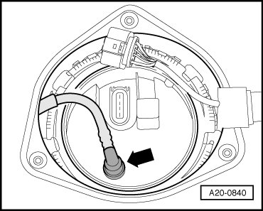
- Remove fuel return line - arrow - from locking flange (left vehicle side).
- Attach adapter (V.A.G 1318/7) 1 on return line.
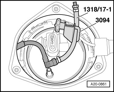
- Use Hose Clamps Up to 25 mm dia. (3094) to clamp adapter (VAG. 1318/17)1.
• The Hose Clamps Up to 25 mm dia. (3094) may not set directly on the fuel line - danger of damage.
- Start engine and run at idling speed.
- Switch ignition off once pressure has built up. At the same time, close cut-off valve of pressure gauge (V.A.G 1318) (lever at right angle to direction of flow).
- Observe pressure drop on gauge.
Pressure drops again:
- If valve is defective, replace fuel pump (check valve defective).
The pressure does not drop:
- Replace fuel filter.
The pressure drops again:
- Check pressure gauge for tightness.
• Before removing the pressure gauge, lower fuel pressure by opening the shut-off valve. Hold container at the connection.
• The assembly of the fuel system is in reverse order of removal.
- Secure fuel hose to connection on fuel rail pipe. To do so, counterhold using an open-end wrench at each hex head - 1 - and - 3 - and tighten union nut - 2 - to 22 Nm.
- Bleed air from fuel system.
Bleed air from fuel system
- Start engine, run it at the middle rpm range for several minutes, and then turn ignition off again.
• The engine may run rough at the beginning because of air in the fuel system.
- Examine fuel system for leakage.
- Check DTC memory, if necessary delete.
Consider the safety precautions. Refer to => [ Safety Precautions ] Multiport Fuel Injection, valid for a test drive.
- Perform a test drive with at least one full load acceleration, after which the fuel system is to be inspected for leaks again.
- After the test drive check the DTC memory again. If a DTC is present again, erase the memory and generate a new readiness code.
- Read readiness code if no DTC is stored. If readiness code is not OK, generate a new one.