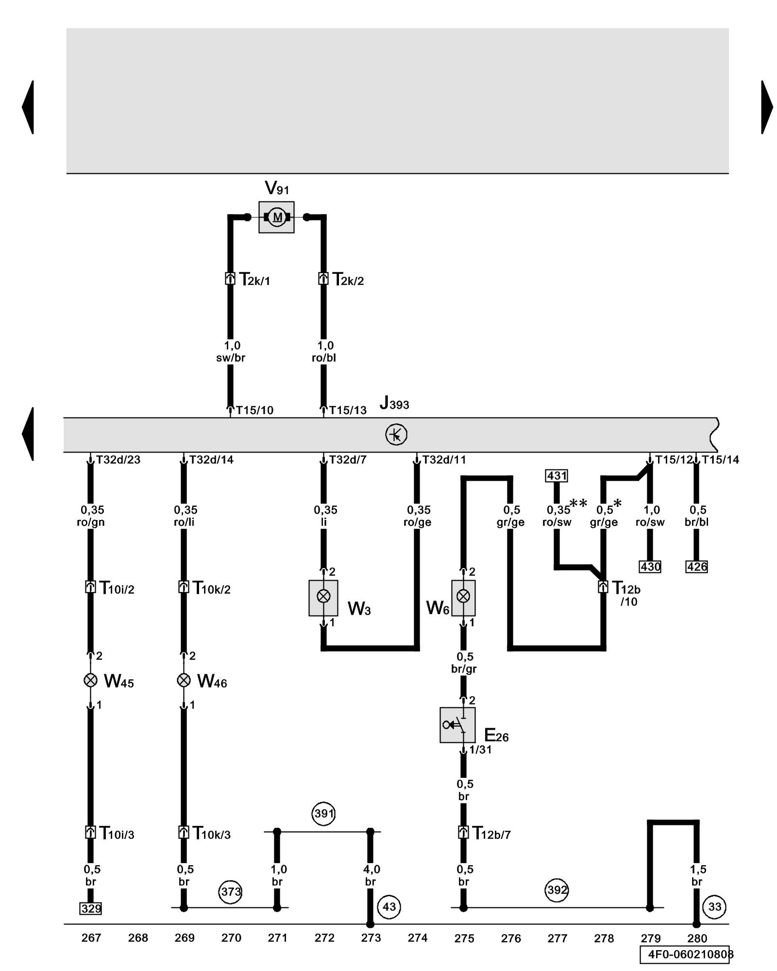
Diagram 60/21 (Tracks 267-280)
IMPORTANT NOTE:
This manufacturer uses "Track" style wiring diagrams.
For information on how to use these diagrams effectively, please refer to Diagram Information and Instructions. Diagram Information and Instructions
Comfort System Central Control Module, Luggage Compartment Light, Left and Right Rear Footwell Light, Glove Compartment Lamp Switch, Glove Compartment Light, Rear Window Shade Motor
ws = white
sw = black
ro = red
br = brown
gn = green
bl = blue
gr = grey
li = lilac
ge = yellow
or = orange
rs = pink
E26 - Glove Compartment Lamp Switch
J393 - Comfort System Central Control Module Overview of Control Modules
T2k - Double Connector, black, D-pillar, left
T10i - 10-Pin Connector, red, left of seat cross member Overview of Connector Stations and Connectors
T10k - 10-Pin Connector, red, right of seat cross member Overview of Connector Stations and Connectors
T12b - 12-Pin Connector, black, behind instrument panel, right
T15 - 15-Pin Connector, brown (Connector A), on comfort system central control module
T32d - 32-Pin Connector, blue (Connector B), on comfort system central control module
V91 - Rear Window Shade Motor
W3 - Luggage Compartment Light
W6 - Glove Compartment Light
W45 - Left Rear Footwell Light
W46 - Right Rear Footwell Light
(43) - Ground Connection (on right lower A-pillar) Overview of Ground Connections in Interior of Vehicle
(373) - Ground Connection 8 (in main wiring harness)
(391) - Ground Connection 26 (in main wiring harness)
(392) - Ground Connection 27 (in main wiring harness)
* - Through May 2007
** - from June 2007
Previous Diagram 60/20 (Tracks 253-266)
Next Diagram 60/22 (Tracks 281-294)