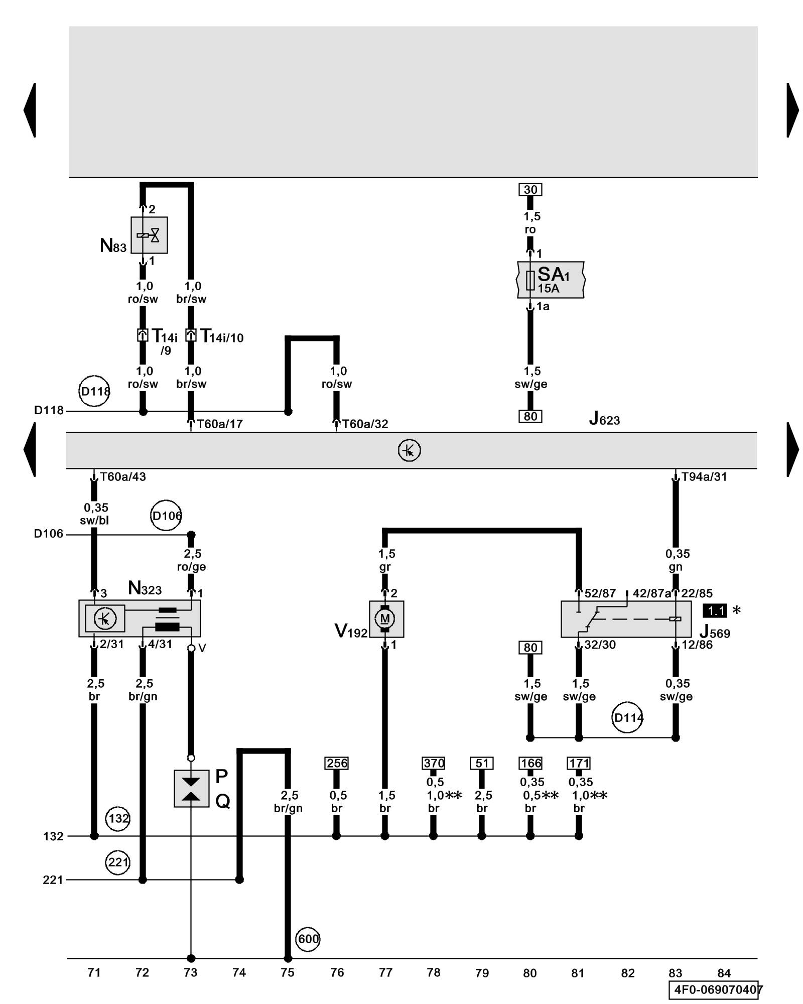
Diagram 69/7 (Tracks 71-84)
IMPORTANT NOTE:
This manufacturer uses "Track" style wiring diagrams.
For information on how to use these diagrams effectively, please refer to Diagram Information and Instructions. Diagram Information and Instructions
Engine Control Module (ECM), Cylinder 5 Fuel Injector, Ignition Coil 5 with Power Output Stage, Brake Booster Relay, Brake System Vacuum Pump
ws = white
sw = black
ro = red
br = brown
gn = green
bl = blue
gr = grey
li = lilac
ge = yellow
or = orange
rs = pink
J569 - Brake Booster Relay Overview of Relay Carrier
J623 - Engine Control Module (ECM) Overview of Control Modules
N83 - Cylinder 5 Fuel Injector 5.2L BXA Overviews
N323 - Ignition Coil 5 with Power Output Stage 5.2L BXA Overviews
P - Spark Plug Connectors
Q - Spark Plugs
SA1 - Fuse 1 (on fuse panel A) Overview of Fuses
T14i - 14-Pin Connector, black, in right engine compartment
T60a - 60-Pin Connector, black (Connector A), on engine control module (ECM)
T94a - 94-Pin Connector, black (Connector B), on engine control module (ECM)
V192 - Brake System Vacuum Pump Locations
(132) - Ground Connection 3 (in engine compartment wiring harness)
(221) - Engine Ground Connection (in engine wiring harness)
(600) - Ground Connection (on cylinder head, right)
(D106) - Connection 4 (in engine compartment wiring harness)
(D114) - Connection 12 (in engine compartment wiring harness)
(D118) - Connection 16 (in engine compartment wiring harness)
* - Relay Carrier Electronics Box (plenum chamber, left)
** - from June 2007
Previous Diagram 69/6 (Tracks 57-70)
Next Diagram 69/8 (Tracks 85-98)