MMI Navigation Plus Information Electronics Control Module 1 (J794) Connectors
MMI Navigation Plus Information Electronics Control Module 1 (J794) Connectors
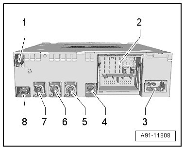
1. GSM connection from roof antenna (R216)
2. Connection Block with Four Connectors
3. MOST bus (T2aw)
4. FBAS IN (T2as) for the DVD changer (R161)
5. 4-pin connector (T4dc) for the front information display control head (J685)
6. 4-pin connector (T4aa) for the external audio source connection (R199)
7. Not Assigned
8. Roof antenna (R216) GPS connection
• Unlisted connector terminals are not used.
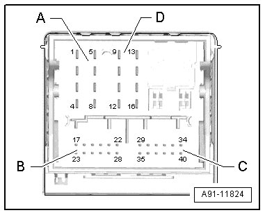
2 - Connection Block With Four Connectors
A - 8-pin Connector (T8h)
3 Wake UP signal to Multimedia system control head (E380).
5 Switch-on signal to the Cellular telephone amplifier (R86) / telephone baseplate (R126).
6 Res MU to Multimedia system control head.
7 Ring-break diagnostic cable.
B - 12-pin Connector (T12g)
2 Microphone input wire (+) from Microphone unit in front roof module (R164) ( right front microphone (R141) )
3 Microphone input wire (-) from the microphone unit in front roof module (right front microphone)
5 FBAS cable (-) for the rearview camera system control module (J772) / peripheral camera control module (J928)
8 Microphone input wire (+) from the microphone unit in front roof module ( left front microphone (R140) )
9 Microphone input (-) from microphone unit in front roof module (left front microphone)
11 CVBS cable (+) for the rearview camera system control module (J772) / peripheral camera control module (J928)
C - 12-pin Connector (T12f)
All pins are connected to the External audio source connection (R199).
1. LF-In ground
2. Right LF-In
3. USB (+5 volt)
4. USB (ground)
5. iPod (ACC Power)
6. Detect
7. Left LF-In
8. LF-In ground shielding
9. FBAS wire (+)
10. FBAS wire (-)
11. iPod data
12. iPod data
D - 8-pin Connector (T8g)
9 Switch-on signal to Telephone baseplate (R126).
10 Data to Multimedia system control head (E380).
11 Data to Multimedia system control head.
12 Terminal 31
13 Telephone baseplate (R126) DIAG signal.
14 Res BT from Multimedia system control head.
15 Terminal 30
3 - MOST bus (T2aw)

1. Output
2. Input
5 - 4-pin Connector (T4aa)

All pins are connected to the External audio source connection (R199).
1. D (+)
2. iPod recognized
3. D (-)
4. Ground
6 - 4-pin Connector (T4dc)
All pins are connected to the Front information display control head (J685).
1. LVDS (-)
2. LIN
3. LVDS (+)
4. Ground