Leak Detection Pump, Checking
Leak Detection Pump, Checking
Observe all safety precautions: => [ Safety Precautions ] Safety Precautions
View clean working conditions: => [ Clean Working Conditions ] Clean Working Conditions
Use only gold-plated terminals when servicing any component with gold-plated electrical harness connector terminals.
For wiring diagrams, component locations, and connector views, Refer to the applicable wiring diagram.
Special tools, testers and auxiliary items required
• Multimeter
• Wiring diagram.
Test requirements
• The Leak Detection Pump (LDP) (V144) fuse OK.
• The ignition switched off.
Test procedure
- Perform a preliminary check to verify the customers complaint. Refer to => [ Preliminary Check ] Preliminary Check.
Start diagnosis
- Remove the left rear wheel housing liner. Refer to appropriate service manual.
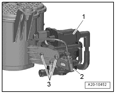
- Disconnect the Leak Detection Pump (LDP) (V144) electrical harness connector - 2 -.
Checking internal resistance
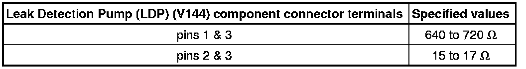
- Using a Multimeter, check the Leak Detection Pump (LDP) (V144) for resistance as follows:

If any of the specified values were not obtained:
- Replace the Leak Detection Pump (LDP) (V144). Refer to appropriate service manual.
- Go to Final procedures
If the specified values were obtained:
Checking voltage supply
• The voltage for the Leak Detection Pump (LDP) (V144) is supplied via the Fuse 7 (on fuse panel B) (SB 7).
- Check the Leak Detection Pump (LDP) (V144) for voltage.
- Using a Multimeter, check the Leak Detection Pump (LDP) (V144) electrical harness connector terminal 3 for voltage.


Switch the ignition ON.
Specified value: Battery voltage.
- Switch the ignition OFF.
If the specified value was not obtained:
- Check the wiring connection for an open circuit or short circuit to Engine ground
- Check the wiring connection for damage, corrosion, loose or broken terminals.
- If necessary, repair the faulty wiring connection and replace any open fuses
- Go to Final procedures
If the specified value was obtained:
Checking wiring
- Remove the Motronic Engine Control Module (ECM) (J623). Refer to appropriate service manual.
- Using a Multimeter, check the Leak Detection Pump (LDP) (V144) electrical connector to Motronic Engine Control Module (ECM) (J623) electrical connector for an open circuit.
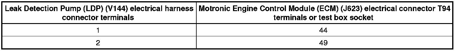
Specified value: 1.5 ohms max.
If the specified values were not obtained:
- Check the wiring connection for an open circuit, short circuit to Battery voltage or Ground
- Check the wiring connection for damage, corrosion, loose or broken terminals.
- If necessary, repair the faulty wiring connection.
- Go to Final procedures
If the specified value was obtained:
- Replace the Motronic Engine Control Module (ECM) (J623). Refer to appropriate service manual.
Final procedures
- Reassembly is performed in the reverse order of the removal.
- Install the left rear wheel housing liner. Refer to appropriate service manual.
- After the repair work, the following work steps must be performed in the following sequence:
1. Check the DTC memory. Refer to => [ Diagnostic Mode 03 - Read DTC Memory ] Diagnostic Modes 01 - 0A.
2. If necessary, erase the DTC memory. Refer to => [ Diagnostic Mode 04 - Erase DTC Memory ] Diagnostic Modes 01 - 0A.
3. If the DTC memory was erased, generate readiness code. Refer to => [ Readiness Code ] Programming and Relearning.