ESP Assembly Overview
ESP Assembly Overview
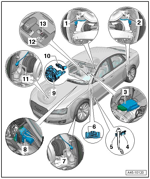
1 Right Rear ABS Wheel Speed Sensor (G44)
• Can be checked in Guided Fault Finding with the Vehicle Diagnosis, Testing and Information System (VAS 505 x).
• Removing and installing, refer to => [ Rear ABS Wheel Speed Sensor ] Rear ABS Wheel Speed Sensor.
2 Left Rear ABS Wheel Speed Sensor (G46)
• Can be checked in Guided Fault Finding with the Vehicle Diagnosis, Testing and Information System (VAS 505 x).
• Removing and installing, refer to => [ Rear ABS Wheel Speed Sensor ] Rear ABS Wheel Speed Sensor.
3 Sensor Electronics Control Module (J849)
• Combined in one housing.
• Component location: Under center console extension.
• Can be checked in Guided Fault Finding with the Vehicle Diagnosis, Testing and Information System (VAS 505 x).
Removing and installing, refer to => [ Sensor Electronics Control Module ] Sensor Electronics Control Module.
4 Brake Lamp Switch (F)
• Component location: On brake pedal.
• Can be checked in Guided Fault Finding with the Vehicle Diagnosis, Testing and Information System (VAS 505 x).
• Removing and installing, refer to => [ Brake Lamp Switch ] Service and Repair
• Cannot be reused after removal.
5 Brake Pedal
• With a mount for the brake lamp switch.
• Removing and Installing, refer to => [ Brake Pedal ] Brake Pedal.
6 Diagnostic Connection
• Component location: Driver side footwell cover.
7 Left Front ABS Wheel Speed Sensor (G47)
• Can be tested in Guided Fault Finding with the Vehicle Diagnosis, Testing and Information System (VAS 505 x).
• Removing and installing, refer to => [ Front ABS Wheel Speed Sensor ] Front ABS Wheel Speed Sensor.
8 ABS Hydraulic Unit (N55) with ABS Control Module with EDL (J104)
• The hydraulic control unit is comprised of the hydraulic unit and control unit.
• Do not disconnect connector (47-pin) before successfully completing self-diagnosis. Switch ignition off before separating connector.
• Component location: On the hydraulic unit in right of engine compartment.
• Removing and installing, refer to => [ Hydraulic Unit with Control Module ] Hydraulic Unit with Control Module.
9 Steering Angle Sensor (G85)
• The steering column electronic systems control module (J527) holds the airbag spiral spring/return spring with slip ring (F138) and the steering angle sensor.
• Removing and Installing, refer to => [ Steering Angle Sensor ] Service and Repair.
10 Return Ring
11 Right Front ABS Wheel Speed Sensor (G45)
• Can be checked in Guided Fault Finding with the Vehicle Diagnosis, Testing and Information System (VAS 505 x).
• Removing and installing, refer to => [ Front ABS Wheel Speed Sensor ] Front ABS Wheel Speed Sensor.
12 -AUTO HOLD- Button (E540)
• Located in the center console.
• Hill start, refer to => [ Hill Start ] Hill Start
• Removing and Installing, refer to => [ Auto Hold Button ] Service and Repair.
13 Parking Brake Contact Switch (F321)
• Component location: In center console.
• Removing and installing, refer to => [ Parking Brake Contact Switch ] Parking Brake Contact Switch.
Explanation of brake system indicator lamps, refer to => [ Brake System Indicator Lamps Overview ] Brake System Indicator Lamps Overview.
Diagnostic Connection
