Removal and Replacement
Active Steering Control Module (J792)
Assembly Overview - Active Steering Control Module

1 Nut, 2.5 Nm
2 Bolt, 8 Nm
3 Active steering control module
4 Connector, clipped to the wiring harness
5 Ground cable
6 Bracket
Special tools, testers and auxiliary items required
• Torque Wrench (V.A.G 1783)
• Vehicle Diagnostic Tester with diagnostic cable
Removing
The active steering control module is located in the footwell in front of the driver seat.
If the active steering control module is replaced, then the program must be started on the vehicle diagnostic tester in "Guided Functions".
- Loosen the driver seat and push it to the rear with the wires still connected.
- Remove the floor mat.
- Remove the sill panel strip..
- Remove the foot rest..
- Remove the cover - 1 - for the emergency release - arrows -.
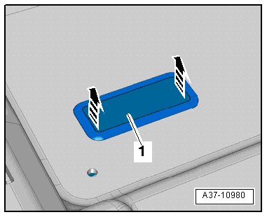
- Disconnect the floor covering and push it to the side, then guide the cover - 1 - for the emergency release through the opening.
- Remove the nuts - arrows -.
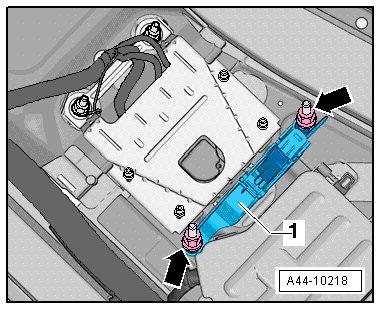
- Swivel the actuator for the emergency release - 1 - to the side.
- Remove nuts - 6 -.
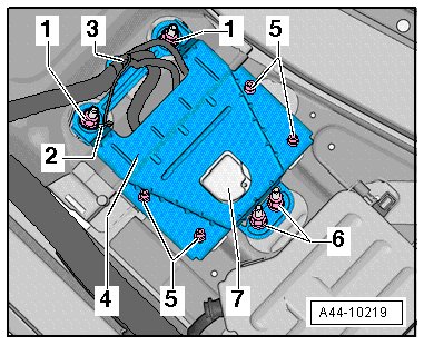
- Remove the nuts - 1 - and remove the Ground (GND) wire - 2 - from the threaded pin.
- Carefully disconnect the wiring harness clip connection - 3 - from the bracket - 4 -.
- Remove the bolts - 5 - from the control module - 7 - and remove the bracket - 4 -.
- Disconnect the wiring harness connector - 3 - from the control module - 7 -.
Installing
Install in reverse order of removal. Note the following:
Tightening specifications
Tightening specifications
Follow the sequence when installing the control module:
- Attach the bracket - 4 - to the control module - 7 - with the bolts - 5 -.
- Connect the wiring harness connectors - 3 - to the control module - 7 -.
- Carefully slide the wiring harness clip connection - 3 - into the bracket - 4 -.
- Insert the control module with the bracket.
- Connect the GND wire - 2 - to the threaded pin and tighten the nuts - 1 -.
- Tighten nuts - 6 -.
- The basic setting must be made if the active steering control module. Refer to => [ Dynamic Steering Basic Setting ] Dynamic Steering Basic Setting.