System Circuit Diagram
System Circuit Diagram
The following block diagram provides an overview of the control modules and bus systems deployed in the vehicle.
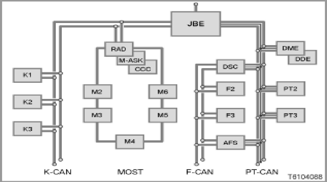
- JBE (Junction Box Electronics)
- Control module with connection to K-CAN, PT-CAN and diagnosis lead
- CCC (Car Communication Computer) or M-ASK (Multi Audio System Controller) or RAD (Radio)
- Control module with connection to K-CAN and MOST
- DSC (Dynamic Stability Control)
- Control module with connection to F-CAN and PT-CAN
- AFS (Active steering)
- Control module with connection to F-CAN and PT-CAN
- K1... Kn: control modules on the K-CAN
- M1... Mn: Control modules on the MOST
- F1... Fn: Control modules on the F-CAN
- PT1... PTn: Control modules on the PT-CAN