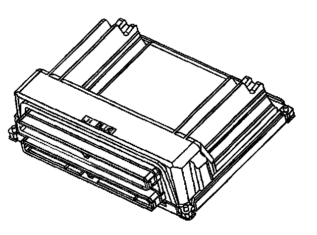
Powertrain Control Module (PCM)
The PCM is responsible for maintaining proper spark and fuel injection timing for all driving conditions. Ignition Control (IC) spark timing is the PCM method of controlling spark advance and ignition dwell. To provide optimum driveability and emissions, the PCM monitors input signals from the following components in calculating Ignition Control (IC) spark timing:
^ Ignition Control module (ICM).
^ Engine Coolant Temperature (ECT) sensor.
^ Intake Air Temperature (IAT) sensor.
^ Mass Air Flow (MAF) sensor.
^ Trans Range or PNP inputs from Trans Range switch or Park/Neutral Position switch.
^ Throttle Position (TP) sensor.
^ Vehicle Speed Sensor (VSS) / Trans Output Speed Sensor (TOSS).
The ignition system uses many of the same ignition module-to-PCM circuits as did previous Delco engine management systems using distributor type ignition. The following describes the PCM to ignition control module circuits:
^ 3X reference PCM input
From the ignition control module, the PCM uses this signal to calculate engine RPM and crankshaft position.The PCM compares pulses on this circuit to any that are on the Reference Low circuit, ignoring any pulses that appear on both. The PCM also uses the pulses on this circuit to initiate injector pulses.
^ 18X reference PCM input
The 18X reference signal is used to accurately control spark timing at low RPM and allow IC operation during crank. Below 1200 RPM, the PCM is monitoring the 18X reference signal and using it as the reference for ignition timing advance. When engine speed exceeds 1200 RPM, the PCM begins using the, 3X reference signal to control spark timing.
^ Camshaft Position PCM input
The PCM uses this signal to determine the position of the cylinder #1 piston during its power stroke. This signal is used by the PCM to calculate true Sequential Fuel Injection (SFI) mode of operation. The PCM compares the number of CAM pulses to the number of 18X and 3X reference pulses. If the number of 18X and 3X reference pulses occurring between CAM pulses is incorrect, or if no CAM pulses are received while the engine is running, the PCM will set DTC P0341. If the cam signal is lost while the engine is running the fuel injection system will shift to a calculated sequential fuel injection mode based on the last cam pulse, and the engine will continue to run. The engine can be re-started and will run in the calculated sequential mode as long as the condition is present with a 1 in 6 chance of being correct.
^ Reference low PCM input
This is a ground circuit for the digital RPM counter inside the PCM, but the wire is connected to engine ground only through the ignition control module. Although this circuit is electrically connected to the PCM, it is not connected to ground at the PCM. The PCM compares voltage pulses on the 3X or 18X reference input to those on this circuit, ignoring pulses that appear on both.
^ Bypass signal PCM output
The ignition control module maintains a fixed spark timing while the engine cranking (Bypass mode). Once the PCM receives 3X reference pulses, the PCM commands the ignition module to allow the PCM to control the spark advance (IC Mode). The ignition control module determines the correct operating mode based on the voltage level that the PCM sends to the ignition control module on the bypass circuit. The PCM provides 5 volts on the bypass circuit if the PCM is going to control spark timing (IC Mode).