Shift Lever - Assemble
ASSEMBLY PROCEDURE- Tools Required
- J 41396 Park Lock Cable Pliers
IMPORTANT: Lubricate all moving parts of the linear shift assembly with synthetic grease.
NOTICE: Refer to Fastener Notice in Service Precautions.

1. Install the gearshift lever assembly support bracket and secure by using 3 flat head 6 lobed socket tap screws.
- Tighten the flat head 6 lobed socket tap screws to 10 Nm (89 inch lbs.).

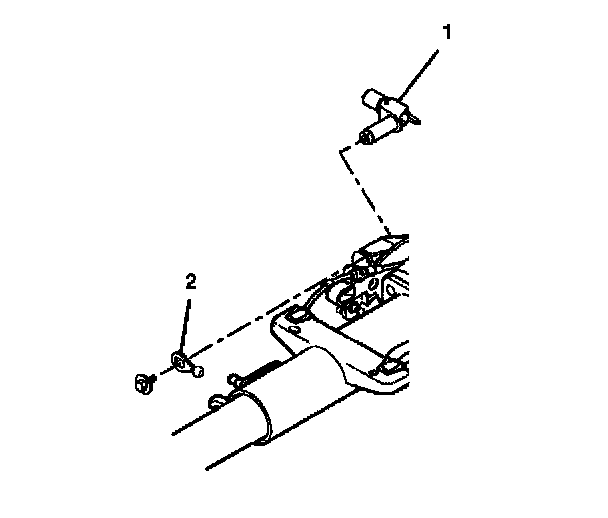
2. Insert the cam bushing (2) into the cable shift cam assembly.
3. Install the cable shift cam assembly (1).
4. Install the hexagon flange head bolt.
- Tighten the hexagon flange head bolt to 18 Nm (14 ft. lbs.).

5. Install the park lock cable assembly.
6. Install the 2 oval head 6 lobed socket tap screws to the gearshift lever assembly support bracket.
- Tighten the oval head 6 lobed socket tap screws to 6.5 Nm (58 inch lbs.).
7. Install the shift lever clevis (1).
8. Install the ball actuator assembly (2).
9. Install the hexagon flanged head bolt.
- Tighten the hexagon flanged head bolt to 18 Nm (14 ft. lbs.).

10. Connect the park lock cable assembly (1) into the lock module assembly.
- The lock cylinder should be in the off-lock position.
- The locking tab at the end of the park lock cable assembly (1) must be installed into the lock module assembly.

11. Adjust the park lock cable assembly using the following steps:
11.1. Use the gear shift lever to put the column in the park position.
11.2. Put the ignition switch in the off-lock position. Remove the key.
11.3. Unlock the adjuster ring (1) on the park lock cable assembly with J41396.
11.4. Pull on the cable until the park lock latch contacts the gear shift lever. Release the cable.
11.5. Lock the adjuster ring (1) securely in place on the park lock cable assembly with J41396.
12. Inspect the park lock cable assembly using the following steps:
12.1. Put the lock cylinder in the off-lock position. The gear shift lever should not be able to shift out of the park position.
12.2. Turn the key to the run position and put the gear shift lever in the neutral position.
12.3. With the gear shift lever in the neutral position the lock cylinder should not be able to go into the off-lock position.
12.4. Put the gear shift lever in the park position.
12.5. Put the lock cylinder in the off-lock position and then remove the key.

13. Install the electrical BTSI actuator. Install the gear shift lever and put the column in the neutral position.

14. Adjust the electrical BTSI actuator using the following steps:
14.1. Pull the tab out on the block side of the electrical BTSI actuator.
14.2. Press on the adjuster block to compress the internal adjuster spring to disengage me adjuster teeth. Slide the adjuster block as far away from the solenoid as possible.
14.3. Lock in place by pushing the tab back in.
15. Inspect the electrical BTSI actuator using the following steps:
15.1. The electrical BTSI actuator must lock the gear shift lever when it is put into the park position.
15.2. When the column is installed in the vehicle you will not be able to shift the gear shift lever out of the park position without pressing on the brake pedal. The solenoid will be energized.
15.3. Readjust if needed.
16. Install the upper and lower shrouds.