Fuel Pump Electrical Circuit Diagnosis
Refer to Engine Controls Schematics.Diagnostic Chart (Part 1 Of 4):
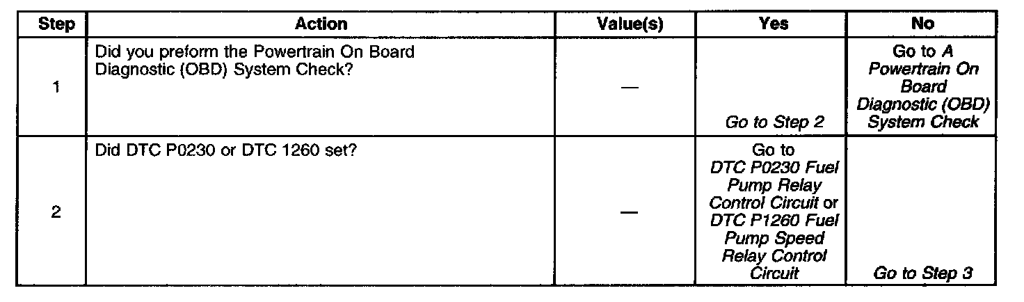
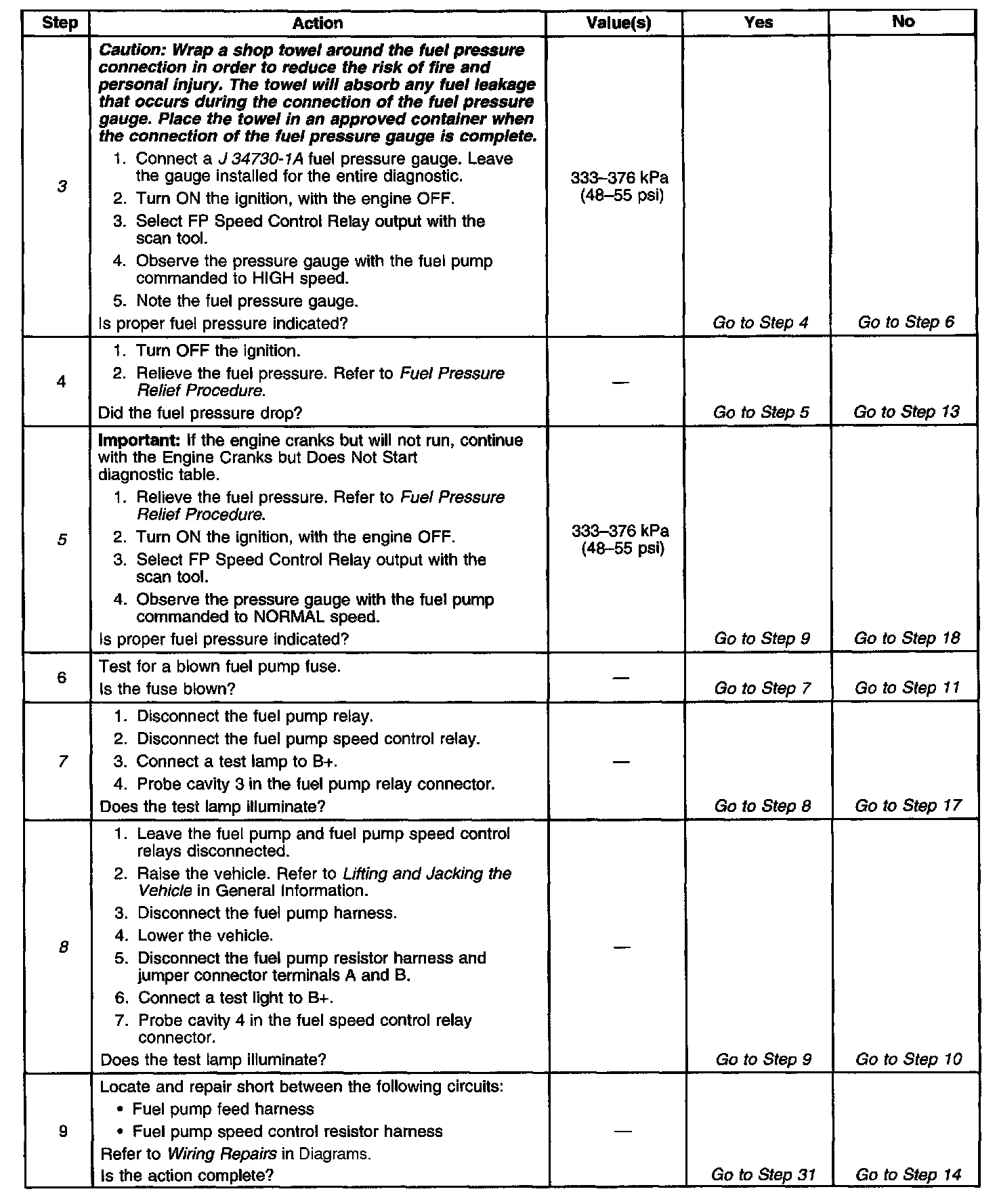
Diagnostic Chart (Part 2 Of 4):
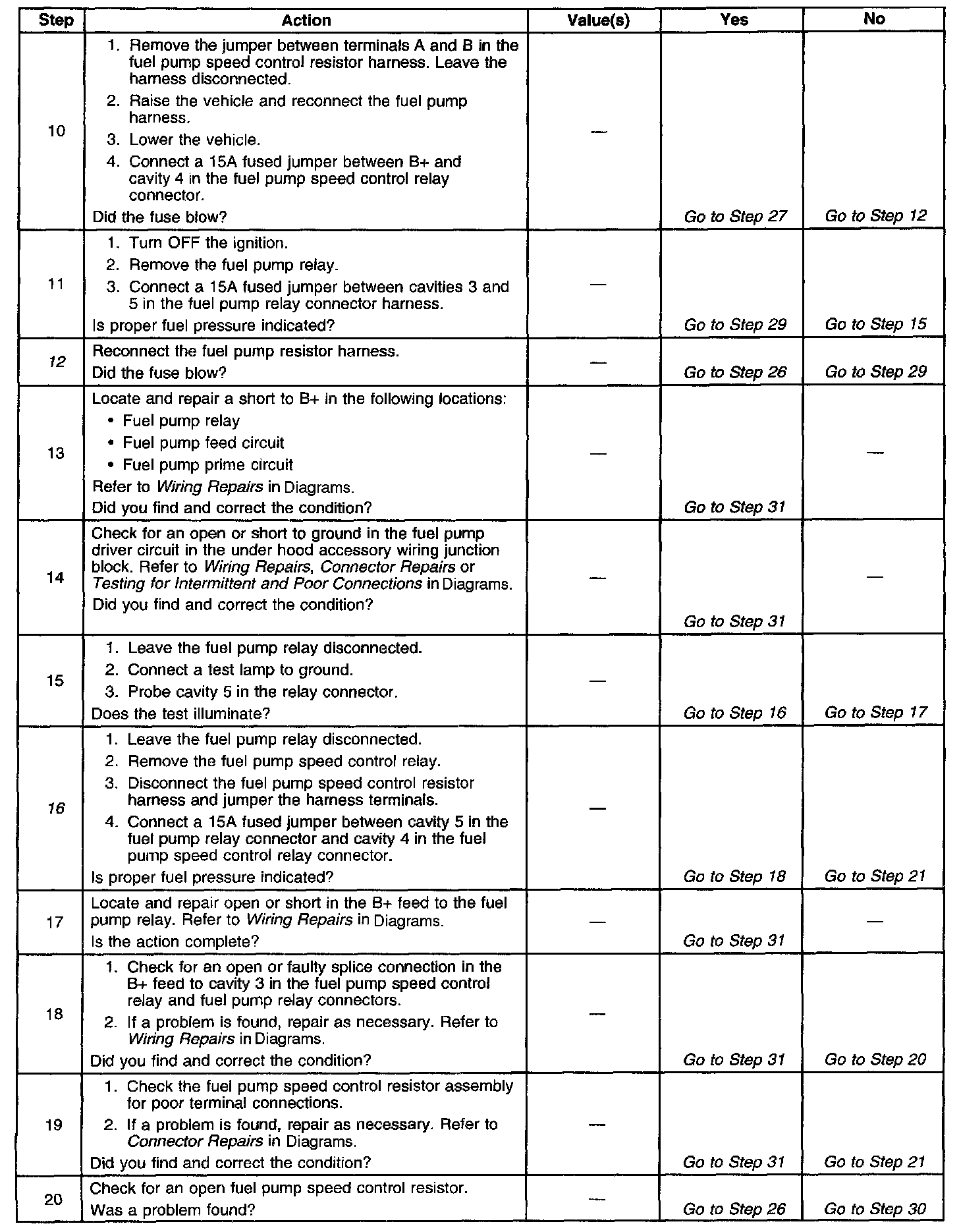
Diagnostic Chart (Part 3 Of 4):
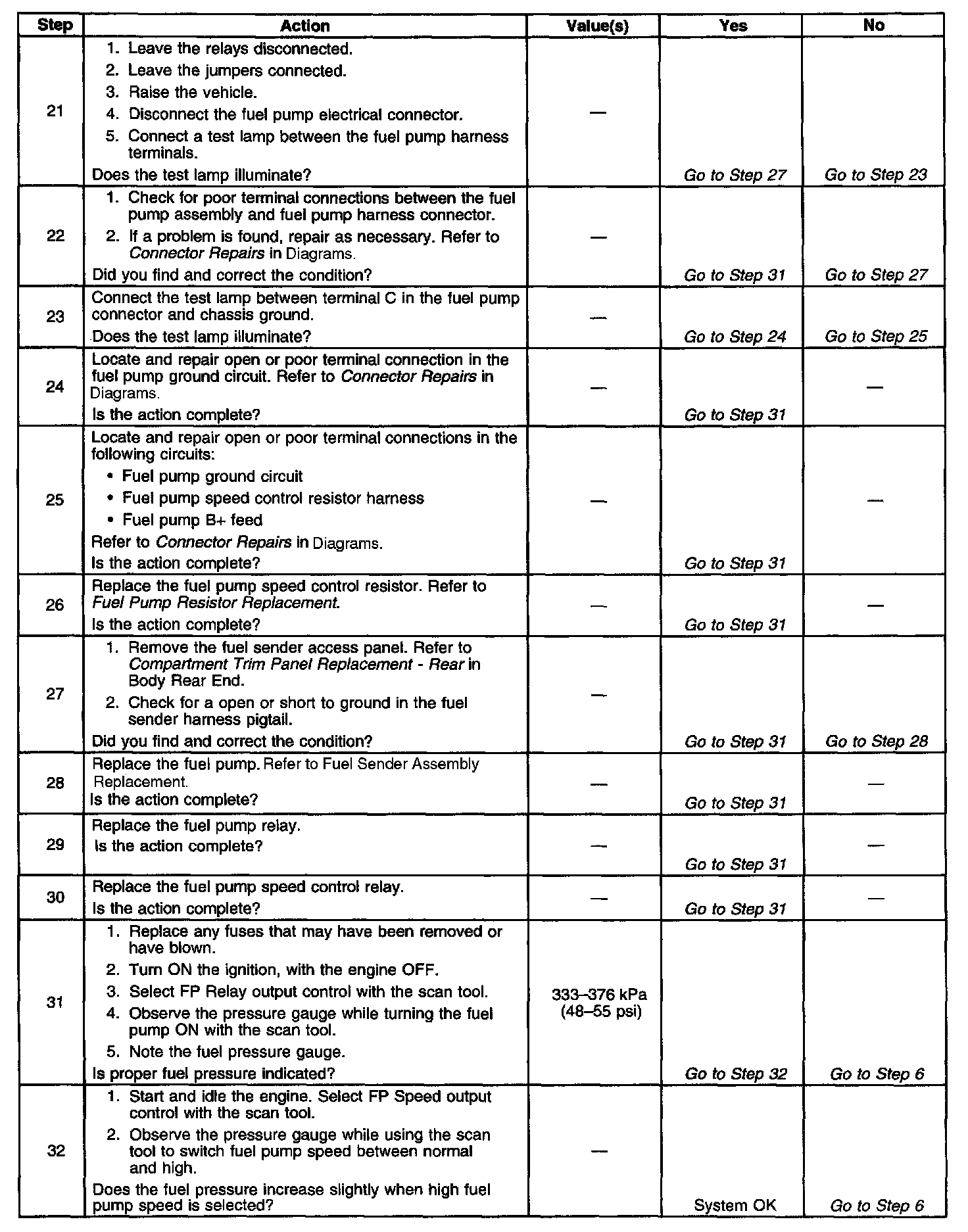
Diagnostic Chart (Part 4 Of 4):
CIRCUIT DESCRIPTION
When the ignition is first turned ON, the Powertrain Control Module (PCM) energizes the fuel pump relay which applies power to the fuel pump through the high speed circuit, controlled by the fuel pump speed control relay. The fuel pump relay will remain ON as long as the engine is running or cranking and the PCM is receiving reference pulses. If no reference pulses are present, the PCM de-energizes the fuel pump relay within 2 seconds after the ignition is turned ON or the engine is OFF. The fuel pump delivers fuel to the fuel rail and injectors, then to the fuel pressure regulator. The fuel pressure regulator controls fuel pressure by allowing excess fuel to be returned to the fuel tank. With the engine OFF, the fuel pump can be turn ON by using the scan tool output controls function.
The PCM alters fuel pump speed by energizing the fuel pump speed control relay. Under normal conditions, the fuel pump speed control relay is energized. The applied voltage to the fuel pump is controlled by a resistor assembly. When higher fuel volume is required due to increased engine load, MAP sensor value over 90 kPa the PCM de-energizes the fuel pump speed control relay circuit. The increased voltage to the in-tank fuel pump allows a higher volume of fuel to be delivered to the fuel rail. The PCM also compensates for low system voltage by energizing the fuel pump speed control relay.
DIAGNOSTIC AIDS
An intermittent may be caused by:
^ A poor connection
^ Rubbed through the wire insulation
^ A wire broken inside of the insulation
Check for a poor connection or a damaged harness - Inspect the PCM harness and connectors for the following items:
^ Improper mating
^ Broken locks
^ Improperly formed or damaged terminals
^ Poor terminal to wire connections
^ Damaged harnesses
TEST DESCRIPTION
The numbers below refer to the step numbers on the diagnostic table.
3. The fuel pump primes the fuel rail/injectors using the high speed circuit. This check ensures proper fuel pressure for the vehicle to start.
5. This step checks for a short to ground in the feed circuit to the fuel pump relay.
7. This step tests for continuity from the fuel pump relay to the fuel pump ground.
8. This step tests for a short to ground in the feed circuit or speed control resistor circuit to the fuel pump.
12. This step tests the fuel pump resistor and resistor pigtail for a short to ground.
16. This step tests the continuity of the speed control and fuel pump feed harness/splices.