Case: Service and Repair
Case Side Cover Replacement
Removal Procedure
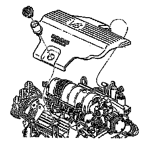
1. Remove the engine sight shield.
2. Remove the air cleaner intake duct. Refer to Air Cleaner Intake Duct Replacement in Engine Controls - 3.8L.

Important: Remove both the throttle and the cruise control cables in order to prevent kinking of the cables during lowering of the transaxle.
3. Remove both the throttle and the cruise control cables (1) from the throttle body and the accelerator control bracket (2).
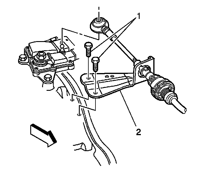
4. Remove the range selector cable from the range selector lever.
5. Remove the range selector cable bracket from the transmission case and set aside.
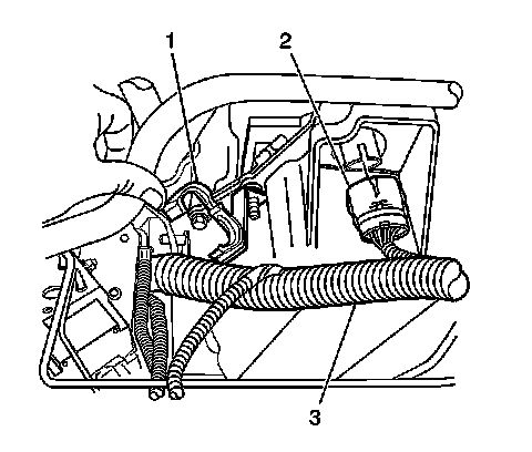
6. Disconnect the transaxle electrical connector C100 (2).
7. Disconnect the wiring harness (3) from the wiring harness retainer (1) on the transaxle.
8. Remove the upper transmission case side cover bolt.
9. Install the engine support fixture. Refer to Engine Support Fixture in Engine Mechanical - 3.8 L.
10. Raise and Support the vehicle. Refer to Vehicle Lifting.
11. Remove the left front tire and wheel assembly. Refer to Tire and Wheel Removal and Installation in Tires and Wheels.
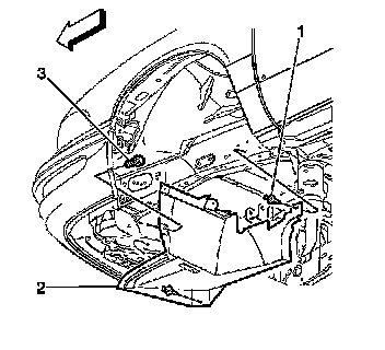
12. Remove the left inner wheelhouse filler (2).
13. Remove the front air deflector. Refer to Air Deflector Replacement - Front in Body Front End.
14. Remove the left ball joint from the steering knuckle. Refer to Lower Control Arm Replacement in Front Suspension.
15. Remove the stabilizer bar links. Refer to Stabilizer Shaft Link Replacement in Front Suspension.
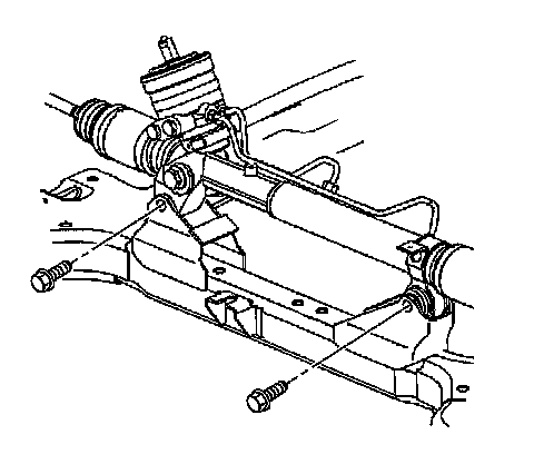
16. Rotate the stabilizer bar to gain access to the power steering mounting bolts.
17. Remove the power steering gear mounting bolts.
18. Remove the power steering line retainers from the frame.
19. Secure the power steering gear to the vehicle body.
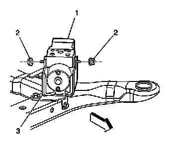
20. Loosen the two mounting nuts (2) in order to allow removal of the brake pressure modulator valve (1) from the bracket (3).
21. Remove the brake line retainers from the frame.

22. Remove the two lower bolts and lower nut from the rear transaxle mount (1).
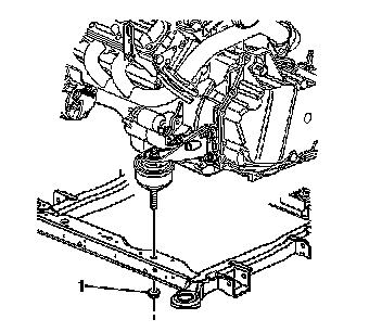
23. Remove the lower nut (1) from the front transaxle mount.
24. Support the left side of the frame with an appropriate jack.

25. Remove the three frame-to-body bolts (3) on the left side.
Important: DO NOT loosen the front and rear frame-to-body bolts on the right side.
26. Loosen, but do not remove, the right center frame-to-body bolt.
Important: Insure that all pipes, hoses and wires are clear and not being bound or stressed when lowering the frame.
27. Lower the left side of the frame.
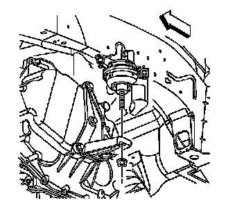
28. Remove the left transaxle mount nut.
29. lower the vehicle enough to gain access to the engine support fixture.
30. Using the engine support fixture, lower the transaxle.
31. Raise the vehicle.
32. Position an oil drain pan under the left side of the transaxle.
33. Remove the left drive axle from the transaxle. Refer to Wheel Drive Shaft Replacement in Wheel Drive Shafts.

34. Remove the case side cover bolts.

35. Remove the case side cover (53).
36. If replacing the side cover, remove the transmission mount bracket. Refer to Transmission Mount Bracket Replacement - Left .
37. Clean the case and side cover gasket surfaces.
Installation Procedure
1. Assemble the case side cover inner gasket (59) to the case side cover (53). Use J 36850 on the seal surfaces.
2. Install the case side cover gasket (54) and case side cover (53) onto the case. Make sure the gaskets and electrical connector are positioned correctly.
3. Install the transmission side case bolts.
Notice: Refer to Fastener Notice in Service Precautions.
Tighten all bolts to 25 Nm (18 lb ft).
4. If removed, install the transmission mount bracket. Refer to Transmission Mount Bracket Replacement - Left .
5. Install the drive axle into the transaxle. Refer to Wheel Drive Shaft Replacement in Wheel Drive Shafts.
6. Lower the vehicle enough to gain access to the engine support fixture.
7. Using the engine support fixture, raise the transaxle to it's original position.
8. Raise the vehicle.
9. Install the left transaxle mount nut.
Tighten the bolts to 80 Nm (59 lb ft).
10. Using an appropriate jack. Carefully raise the left side of the frame so that the frame-to-body bolts can be installed.
11. Using 16 mm (0.630 inch) dowel pins in the alignment holes (1), align the engine frame (2) with the body.
12. Install the frame-to-body bolts (3).
Tighten the bolts to 112 Nm (83 lb ft).
13. Remove the jack stand and oil drain pan.
14. Install the lower nut (1) onto the front transaxle mount.
Tighten the nut to 70 Nm (52 lb ft).
15. Install the two lower bolts and lower nut onto the rear transaxle mount (1).
Tighten the two lower bolts and lower nut to 50 Nm (37 lb ft).
16. Position the brake pressure modulator valve (1) into the bracket (3).
Tighten the two nuts (2) to 10 Nm (89 lb in).
17. Install the brake line retainers onto the frame.
18. Install the power steering gear mounting bolts.
Tighten the bolts to 70 Nm (95 lb ft).
19. Install the power steering line retainers onto the frame.
20. Install the ball joint into the steering knuckle. Refer to Lower Control Arm Replacement in Front Suspension.
21. Install the stabilizer bar links. Refer to Stabilizer Shaft Link Replacement in Front Suspension.
22. Install the front air deflector. Refer to Air Deflector Replacement - Front in Body Front End.
23. Install the left inner wheelhouse filler (2).
24. Install the left front tire and wheel assembly. Refer to Tire and Wheel Removal and Installation in Tires and Wheels.
25. Lower the vehicle.
26. Remove the engine support fixture.
27. Install the upper transmission side case bolt.
Notice: Refer to Fastener Notice in Service Precautions.
Tighten all bolts to 25 Nm (18 lb ft).
28. Connect the transaxle electrical connector C100 (2).
29. Install the wiring harness (3) into the wiring harness retainer (1) on the transaxle.
30. Install the range selector cable bracket to the transmission case.
31. Install the range selector cable to the range selector lever.
32. Install the range selector cable bracket bolts.
Tighten the bolts to 25 Nm (18 lb ft).
33. Check adjustment of the range selector cable. Re-adjust as needed.
34. Install the throttle and cruise control cables (1) into the throttle body and the accelerator control bracket (2).
35. Install the engine sight shield.
36. Install the air cleaner intake duct. Refer to Air Cleaner Intake Duct Replacement in Engine Controls - 3.8L.
37. Fill the transaxle to the proper level. Refer to Fluid Capacity Specifications .
38. Inspect the transaxle fluid level.
39. Inspect for fluid leaks.