A/T - Code P028, Intermittent Loss of Drive or Downshift
Bulletin No.T-92-117
File in Group
7
Number
241
Corp. Ref. No.
277124
Date
August, 1992
SUBJECT
PCM CODE P028, INTERMITTENT LOSS OF DRIVE, OR INTERMITTENT DOWNSHIFTS TO SECOND GEAR (REPLACE TRANSAXLE PRESSURE SWITCH)
MODELS AFFECTED:
1993 ALLANTES WITH HYDRA-MATIC 4T80-E TRANSAXLE
Some 1993 Allantes with the Hydra-Matic 4T80-E transaxle may experience a PCM Diagnostic Trouble Code P028 caused by an erratic signal from the transaxle pressure switch. The transaxle pressure switch may also cause the PCM to intermittently default the transaxle to second gear, with or without a code setting. This may cause the following transaxle conditions:
1. At highway speeds (third or fourth gear) the second sprag clutch will overrun and the transaxle will seem as if it is in "NEUTRAL" until code P028 sets. This may be described as an "intermittent loss of drive".
2. At lower speeds (second gear available) the driver will sense the vehicle slowing and will tend to increase throttle angle until second gear is achieved.
3. If at any time the PCM reads a transaxle pressure switch signal that rapidly changes back and forth between a valid and an illegal value, the transaxle will "hunt" between gears. This will cause code P028 to take longer to set.
To diagnose this condition perform the following procedure:
1. Refer to PCM Diagnostic Trouble Code Chart P028 in Section 6E-A of the 1993 Allante Service Information Manual.
2. Follow the code P028 diagnostic chart to determine the cause of the condition. This condition may be caused by a wiring problem, so following the code P028 diagnostic chart is important to assure proper repair.
3. If the code P028 diagnostic chart indicates transaxle pressure switch replacement or an intermittent condition, install service transaxle pressure switch. Refer to the Service Procedure and the Parts Information in this bulletin.
Service Procedure:
To replace the transaxle pressure switch perform the following procedure:
1. Raise vehicle and support.
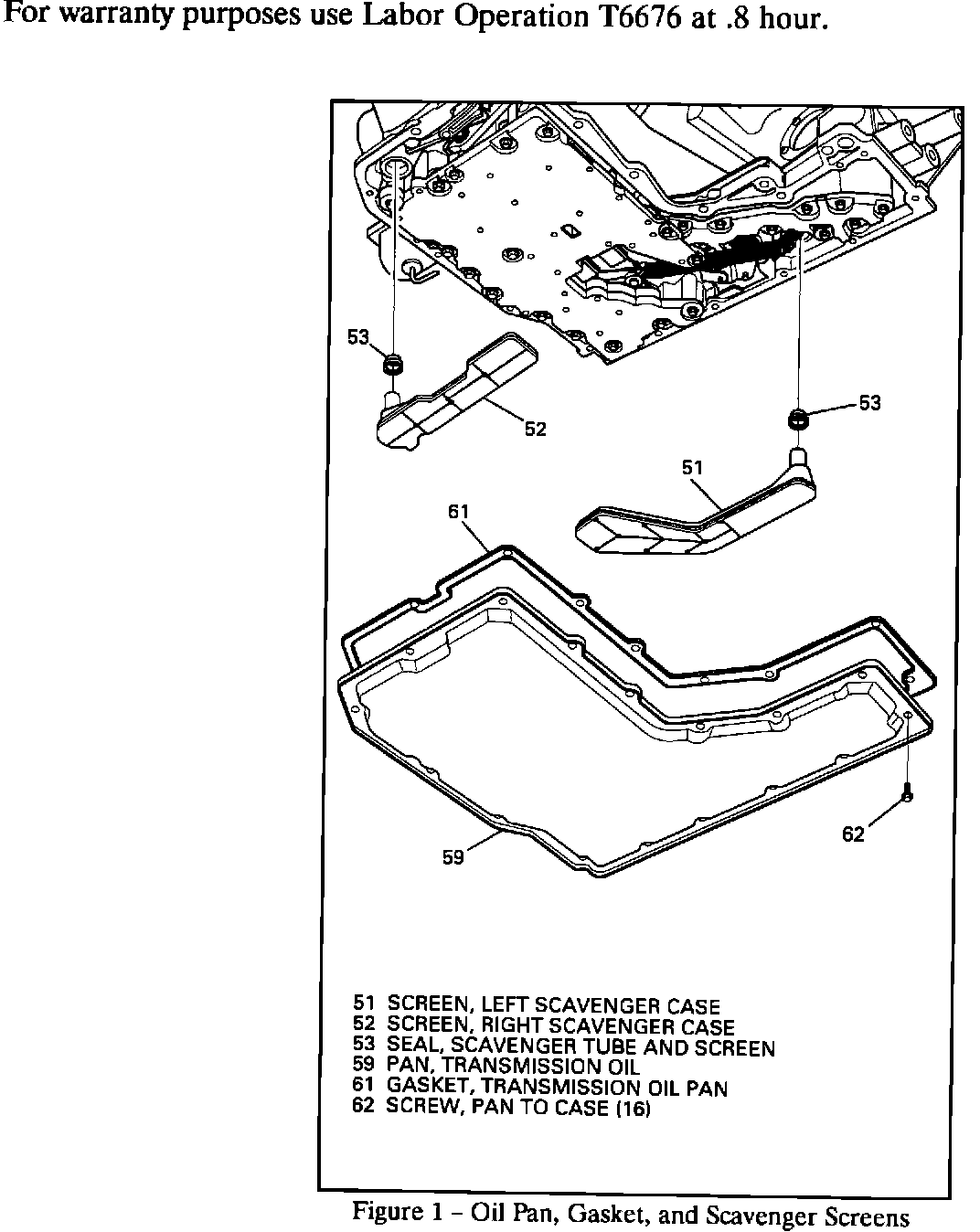
2. Remove 16 bottom pan bolts (62), bottom pan (59), and gasket (61). Allow transmission fluid to drain and discard gasket. Refer to Figure 1.
3. Remove left and right scavenger screens (51, 52) and seals (53) and discard. Do not score or damage case when removing seals. Refer to Figure 1.
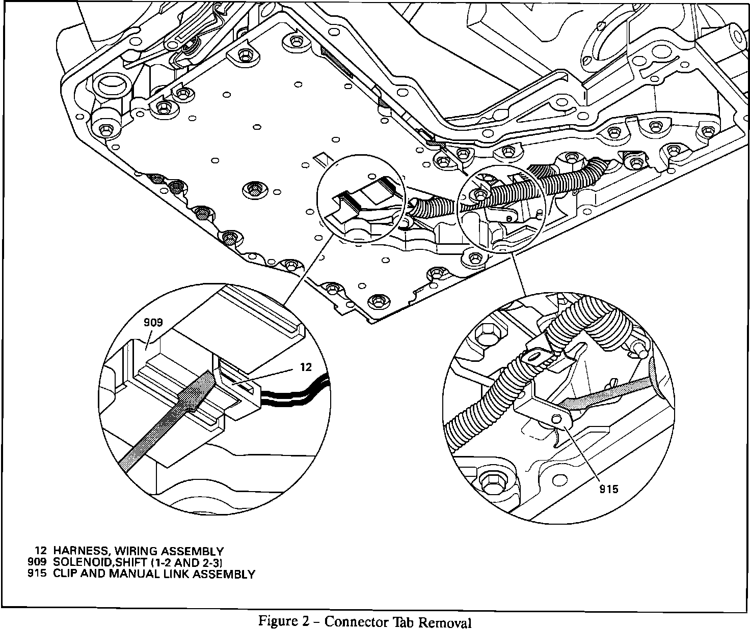
4. Disconnect shift solenoids A, B, and transaxle pressure switch connectors. Refer to Figure 2.
5. Disconnect manual valve linkage clip (915). Refer to Figure 2.
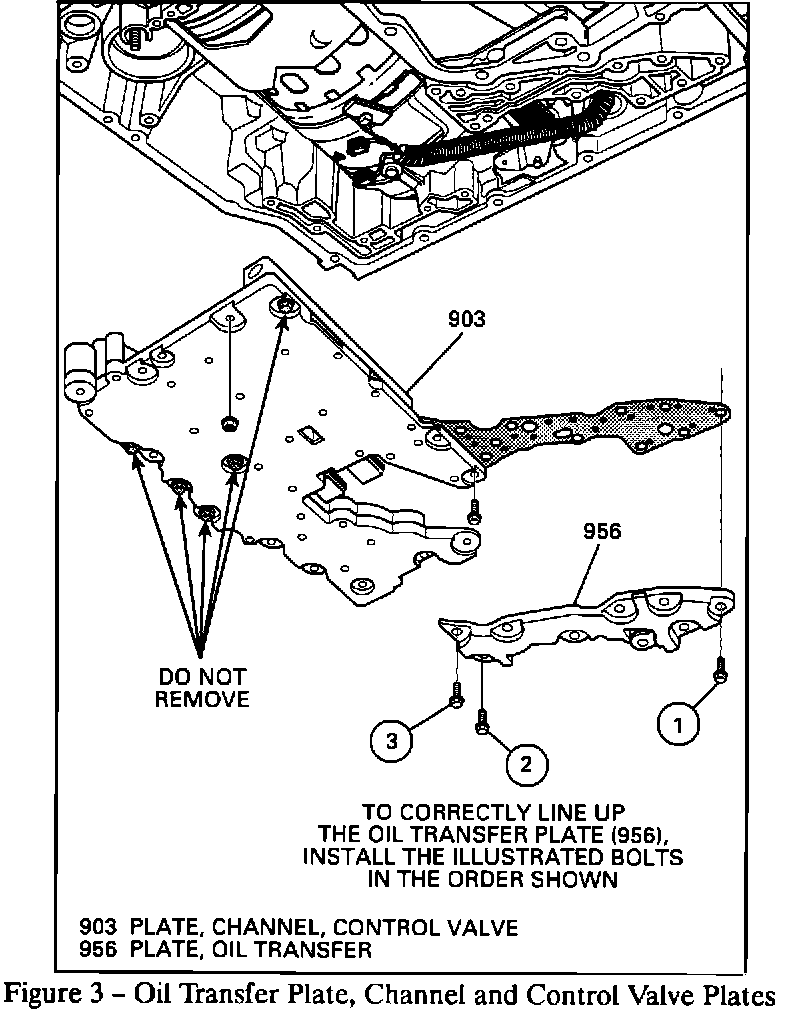
6. Remove nine oil transfer plate bolts and oil transfer plate (956). Refer to Figure 3.
7. Remove ten lower channel plate bolts (534), two nuts (995) and lower channel plate control valve, and accumulator assembly from transaxle. DO NOT REMOVE indicated bolts in lower channel plate. Refer to Figure 3.
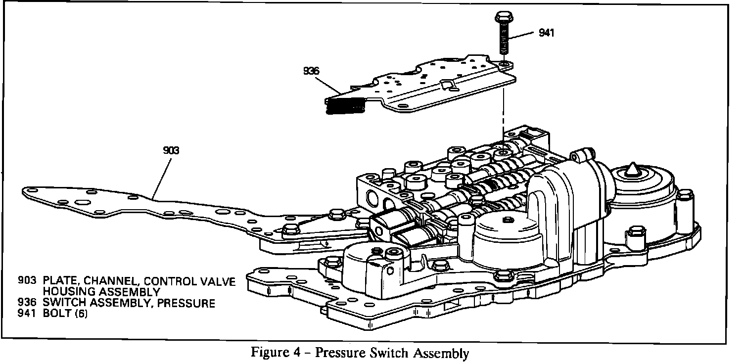
8. Remove six bolts (941) and transaxle pressure switch (936). Refer to Figure 4.
9. Install new transaxle pressure switch (936) and six bolts (941). Torque bolts to 12 N-m (106 lbs. ft.).
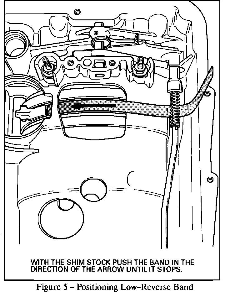
10. Position the low reverse band using a 12 inch length of .020" shim stock. A mispositioned low reverse band during reassembly will result in a "no reverse" or "slips in reverse" condition. Refer to Figure 5. NOTE: Do not remove shim stock until step 12.
11. Place lower channel plate, control valve, and accumulator assembly in transaxle using the forward support studs to locate.
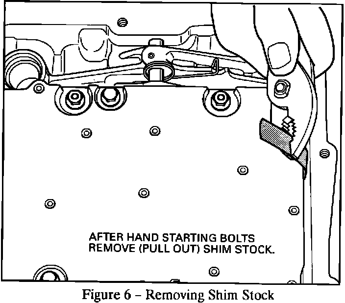
12. Hand start ten bolts and two nuts into channel plate. Bolts without flanges are located next to oil transfer plate. Torque bolts and nuts to 12 N-m (106 lbs.in.). Remove shim stock. Refer to Figure 6.
13. Install oil transfer plate and hand start nine bolts. Torque bolts to 12 N-m (106 lbs.in.).
14. Connect manual valve (915) to detent lever (17). Refer to Figure 2.
15. Route wiring harness under spacer plate rib and detent lever. Connect wiring harness to shift solenoids A, B (909), and transaxle pressure switch (936). Refer to Figure 2.
16. Install left and right scavenger screens (51, 52) and seals (53). Refer to Figure 1.
17. Remove any residual transmission fluid from the gasket sealing surface of the case, the outside surface of the case, case bolt holes, bottom pan, and bolts. Use a rubber-tipped air hose on the case bolt holes to remove fluid, if necessary. All of the bottom pan bolts MUST be completely dry before installation.
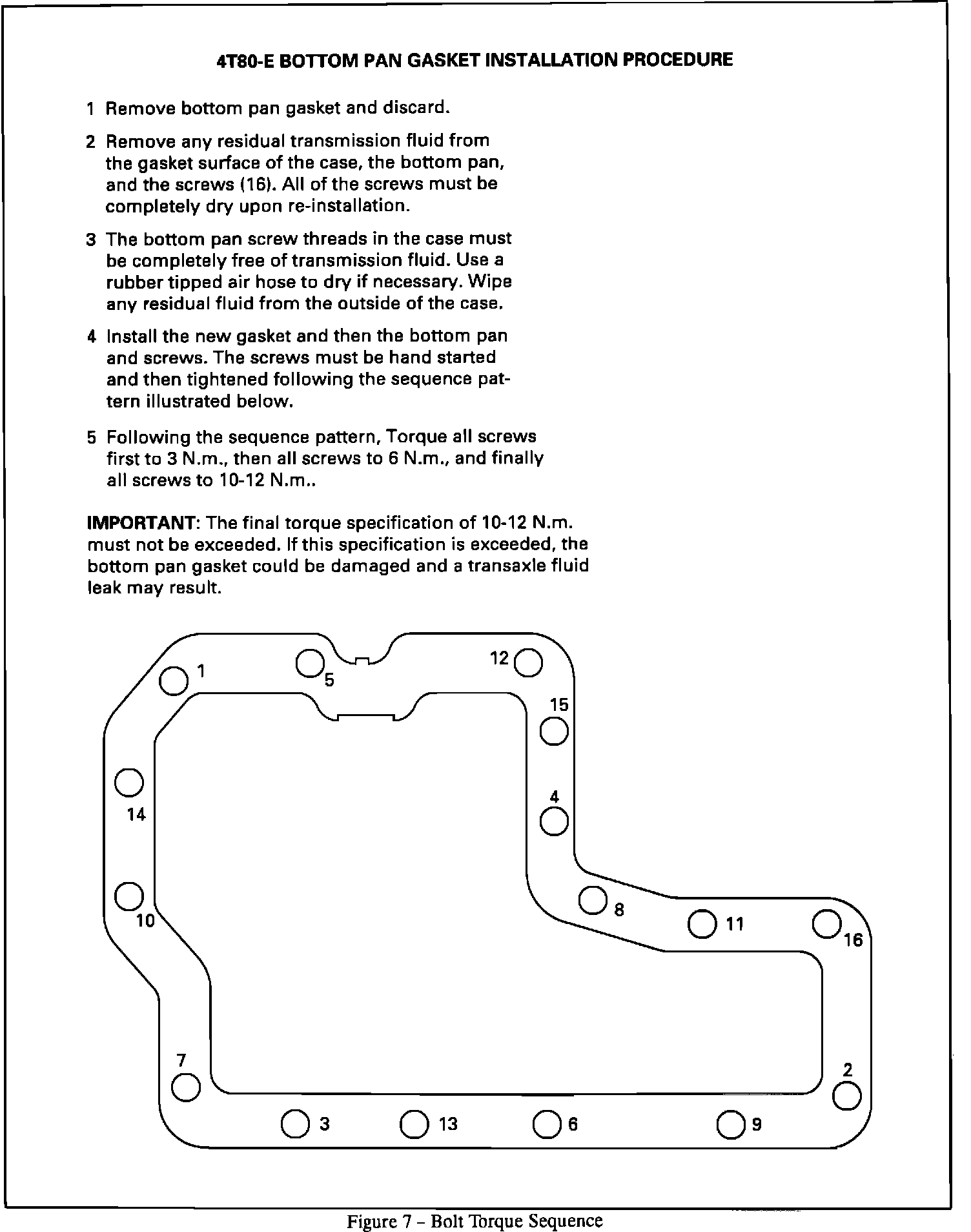
18. Position the new gasket and bottom pan on the transaxle. Hand start all of the bottom pan bolts, then follow the torque sequence listed below. Refer to Figure 7.
^ Torque all bolts first to 3 N-m (27 lbs.in.), then to 6 N-m (53 lbs.in.), and finally to l2 N-m (106 lbs.in.).
IMPORTANT:
The final torque specification of 12 N-m (106 lbs.in.) must not be exceeded. If this specification is exceeded, the bottom pan gasket and case could be damaged and a transmission fluid leak may result.
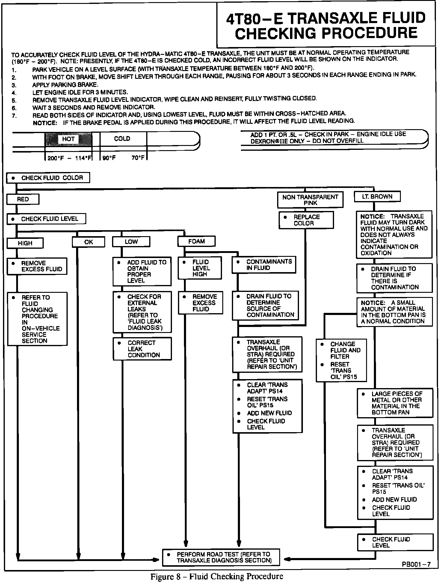
19. Lower vehicle and fill transaxle with DEXRON II-E transmission fluid. Start by adding four quarts of fluid, top off as needed to reach the proper operating level. Refer to Figure 8.
Parts Information:
Description P/N
Tansaxle Pressure Switch 8683880
Bottom Pan Gasket Kit (includes gasket, 8684953
left and right scavenger screens, and seals)
Parts are currently available from GMSPO. Part numbers are accurate at time of printing and are subject to change.