PCM Controlled Tachometer Diagnosis
Refer to Diagrams for wiring view. Electrical Diagrams
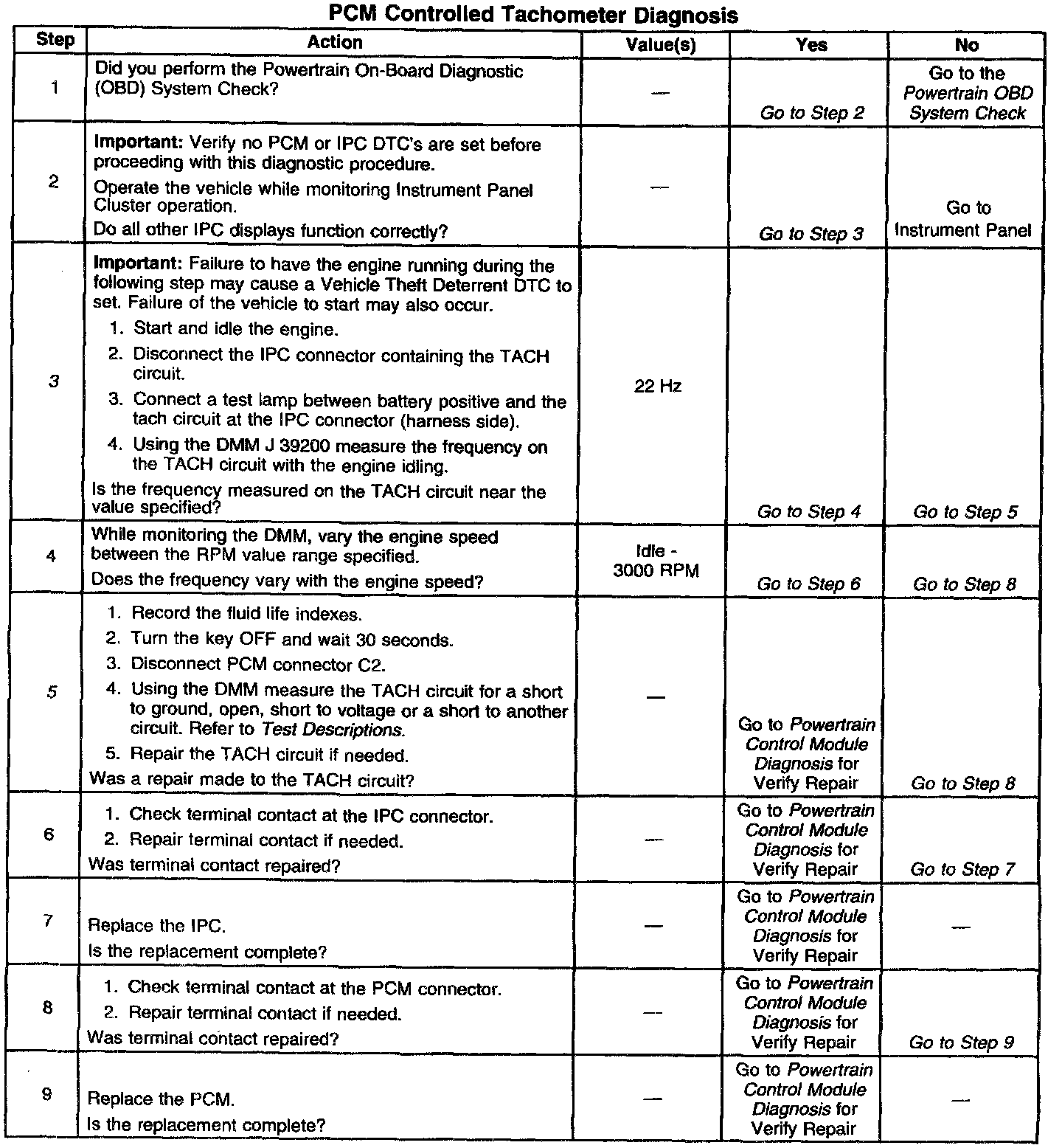
Circuit Description
The Instrument Panel Cluster (IPC) supplies 12 volts to the TACH circuit. The PCM Pulse Width Modulates (PWM) this circuit. This PWM signal varies with the speed of the engine.
Test Description
3. Connecting a test lamp in series between battery voltage and the tach circuit to the PCM allows the PCM to create the PWM signal on the tach circuit. With normal circuit operation the test lamp will pulse while running. A higher engine speed will create a faster pulse of the test light.
5. When checking for shorts to ground, resistance of more than 10K ohms is usually acceptable although most readings should be infinite (OL).
When checking for circuit continuity (opens) resistance should be 5 ohms or less.
When checking for shorts to voltage take measurements with the ignition ON and OFF.
Disconnect the circuit from all components before performing any circuit check.
Always check or zero the meter before performing resistance checks.