EGR System Description
PurposeThe Exhaust Gas Recirculation (EGR) system is used in automotive engines to decrease the emission levels of oxides of nitrogen (NOx). NOx defines a group of chemical compounds containing nitrogen and varying amounts of oxygen that can have harmful environmental effects in large quantities.
NOx forms during the combustion process in amounts that are dependent on the concentration of oxygen in the combustion chamber and the duration that the combustion process temperatures exceed 1500°F. Decreased NOx levels are accomplished by reducing the peak combustion temperatures through dilution of the incoming fuel/air charge with exhaust gas. When re-introduced into the combustion chamber, the exhaust gas (largely non-reactive carbon dioxide and water vapor) acts to absorb a portion of the combustion energy. This results in lower peak combustion temperatures throughout the combustion process and lower yield amounts of NOx.
Desired amounts of EGR depend upon the geometry of the combustion chamber and the operating condition of the engine. Extensive laboratory and vehicle tests are used to determine optimal EGR rates for all operating conditions. Too little EGR can yield high NOx, while too much EGR can disrupt combustion events. This engine uses a computer controlled valve to regulate the amount of EGR delivered to the engine under all operating conditions.
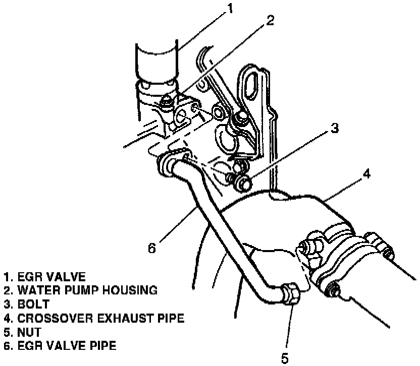
EGR Valve Pipe:
Operation
Exhaust gases are routed to the engine through the corrugated semi-flexible feed pipe which connects the crossover exhaust pipe to the crossover water pump housing.
EGR Flow Diagram:
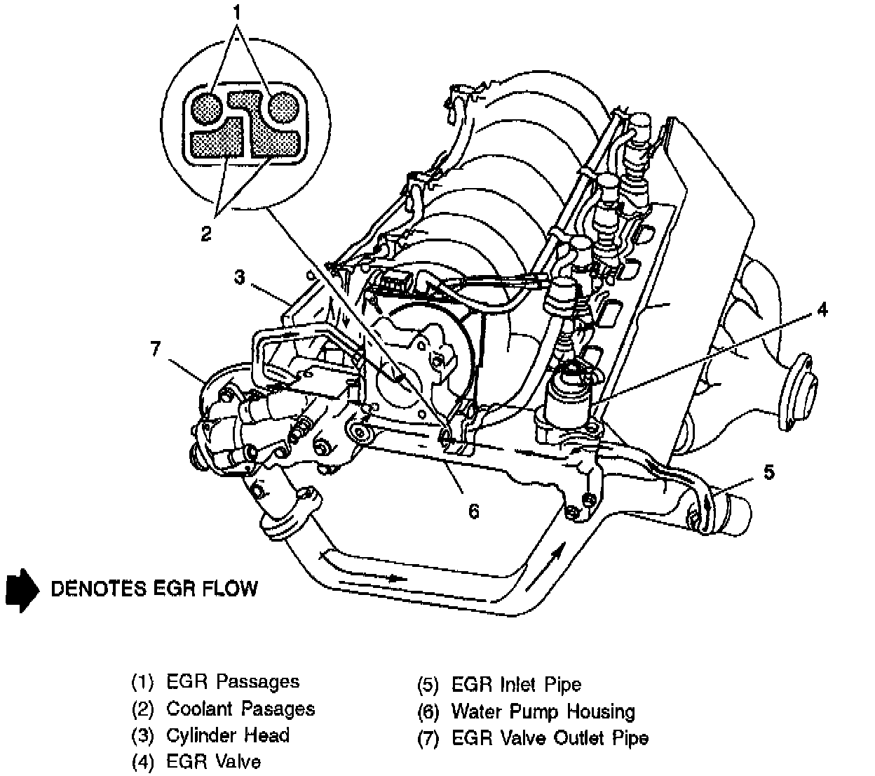
In the crossover water pump housing, as shown in the EGR Flow figure, exhaust gases are precisely metered by the PCM controlled EGR Valve, then cooled by engine coolant and finally routed into the throttle body spacer through another corrugated semi - flexible feed pipe from the water pump crossover. A potential drawback with EGR is that for certain driving schedules, deposits can accumulate when hot exhaust gases are cooled. The system uses the
crossover water pump housing as a cross-flow heat exchanger to cool exhaust gases in large easily cleaned passages to virtually eliminate any concern with deposit accumulation during the service life of the engine. This is done by having the cooling passage reduce EGR gasses below their deposit forming temperature prior to routing these gasses into the throttle body spacer.
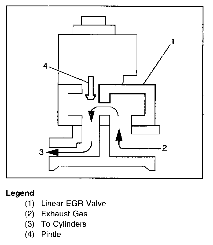
Engine vacuum draws exhaust gases through the EGR feed pipe into the throttle body spacer where they mix with the incoming air charge and are distributed equally to each cylinder.
EGR Valve Assembly Sectional View:
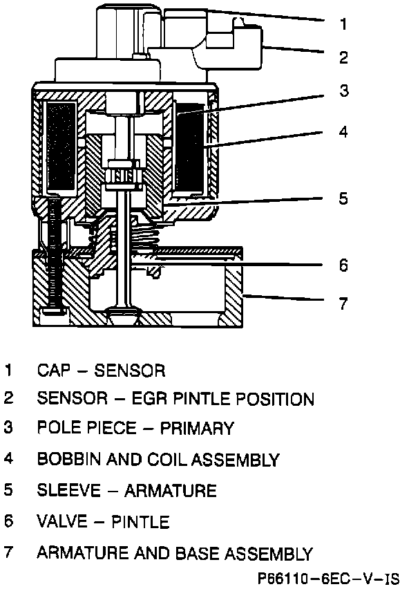
The EGR Valve regulates the amount of exhaust gas fed to the engine. This mixture is dependent upon the height of the pintle above the orifice in the base of the valve.
The bobbin and coil (solenoid) assembly is encapsulated to maximize reliability, to seal the coil from the environment, and to prevent movement of the coil and terminals. Inside the solenoid (bobbin and coil) assembly is an armature assembly, consisting of a pintle and valve assembly, two seals, retaining washers, a seal spring, an armature spring, and a bearing. The valve pintle shaft is sealed from the exhaust chamber by a bearing. In addition, an armature shield, held in place by a compression spring, deflects exhaust gas from the shaft and the armature. The base adapter and base plate make up the base assembly.
As mentioned above the PCM controlled EGR Valve regulates the amount of exhaust gas fed to the engine. This device offers more precise EGR flow metering than a back pressure or digital type valve and superior emission control and driveability.