Mirror Face Replacement
REMOVAL PROCEDURE
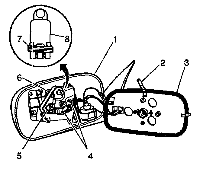
1. Remove the standard electrochromatic mirror glass assembly (3) from the housing of the outside rear view mirror assembly.
^ Manually tilt the mirror glass assembly in the direction of the electrical connectors.
^ Insert your fingers behind the mirror glass and pull the assembly straight out of the housing.
2. Disconnect the electrical connectors.
3. If one or both of the actuator shaft(s) (5,8) come off with the mirror glass assembly perform the following procedure:
^ Push the actuator in the direction of one of the two slots of the molded ring where the actuator ball attaches to the mirror glass assembly.
^ Ensure that the actuator springs (7) are not pushed down on the actuator shafts but are seated in the groove provided.
^ Install the actuator shaft(s) (5,8) on to the mirror assembly power drive unit (6) by rotating and pressing the actuator on to the power drive unit.
INSTALLATION PROCEDURE
1. Connect the electrical connectors to the new standard electrochromatic mirror glass assembly (3).
2. Rotate the actuator shaft(s) on the power drive unit to align the flats on the actuator ball with the corresponding slots of the molded rings on the back of the mirror glass assembly.
3. Install the standard electrochromatic mirror glass assembly (3).
^ Ensure the spring fingers (2) are inside the housing assembly (1).
^ Align the actuators (5,8), memory plungers (4) and the center pivot point on the power drive unit (6) with the corresponding attachment points on the mirror glass assembly (3).
^ Support the mirror assembly housing and firmly press the mirror glass assembly with enough force to engage the center pivot point on to the power drive unit.
4. Install the upper (vertical) actuator shaft (8) and memory plunger (if vehicle is equipped with RPO A45) by applying pressure approximately 1 inch from the top and center of the mirror glass with both thumbs until an audible snap is heard.
5. Install the side (horizontal) actuator shaft (5) and memory plunger (if vehicle is equipped with RPO A45) by applying pressure approximately 2 inches from the outboard edge of the mirror glass with both thumbs until an audible snap is heard.
6. Ensure all functions are operating correctly by electrically actuating the outside rear view mirror assembly. (Up, down, left, right and memory if vehicle is equipped with RPO A45.)