Engine Replacement
Engine Replacement
Tools Required
- J 42640 Steering Column Anti-Rotation Pin
- J Engine Lift Brackets
Removal Procedure
1. Center the steering wheel.
2. Turn the ignition OFF.
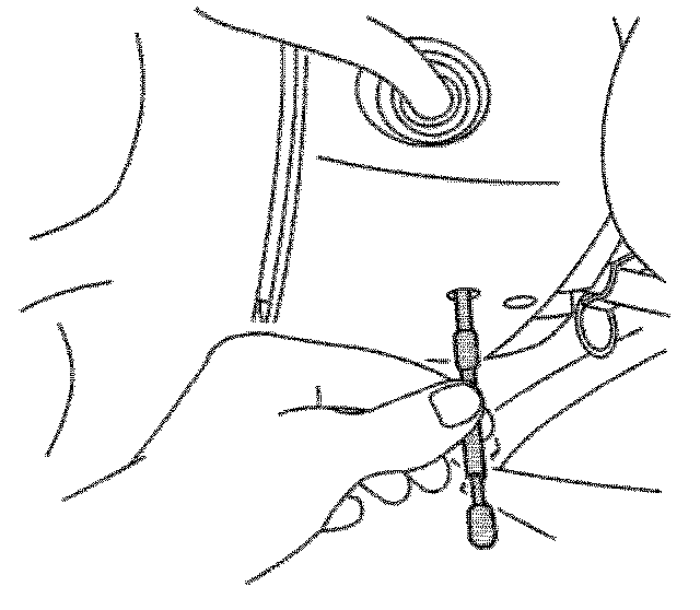
3. Install the J 42640 to the steering column. Refer to: Service and Repair
Important: Do NOT disconnect the battery cable from the engine.
4. Disconnect the battery negative cable from the battery and the body.
Important: Do NOT disconnect the battery cable from the engine.
5. Disconnect the battery positive cable from the battery and the underhood electrical center.
6. Position and secure the battery cables to the engine.
7. Remove the battery.
8. Remove the fuel injector sight shield. Refer to: Service and Repair
9. Remove the air cleaner duct. Refer to: Service and Repair
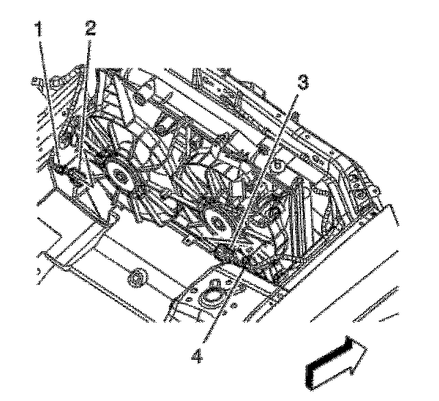
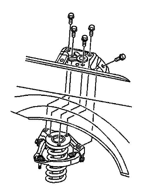
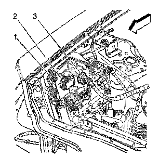
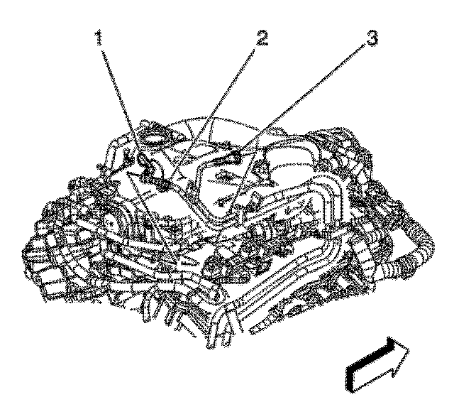
10. Disconnect the cooling fan electrical connectors (2 and 3).
11. Remove the cooling fan wiring harnesses (1 and 4) from the fan shroud.
12. Secure the wiring harnesses to the vehicle.
13. Drain the cooling system. Refer to: Service and Repair
Important: Do NOT disconnect the surge hoses from the engine or the radiator.
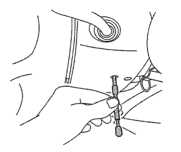
14. Disconnect the surge tank outlet hose from the surge tank. Refer to: Service and Repair
15. Position and secure the surge hose to the engine.
16. Disconnect the surge tank inlet (vent) hose from the water outlet housing and the radiator.
17. Position and secure the surge tank inlet (vent) hose to the vehicle.
18. Disconnect the heater hoses from the heater core. Refer to: Service and Repair

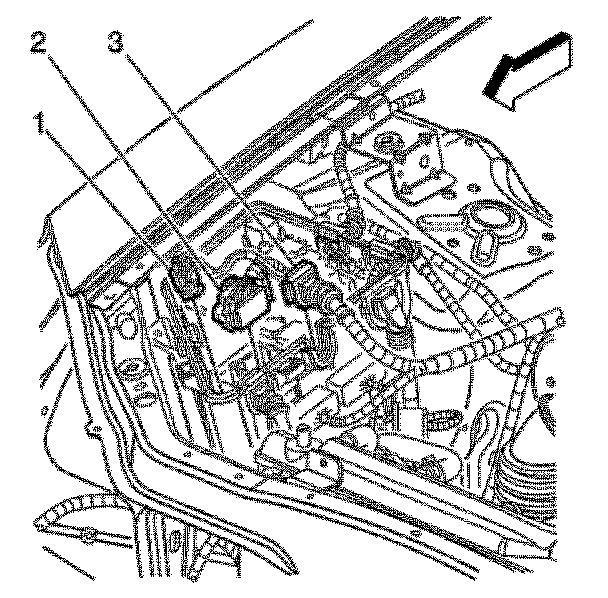
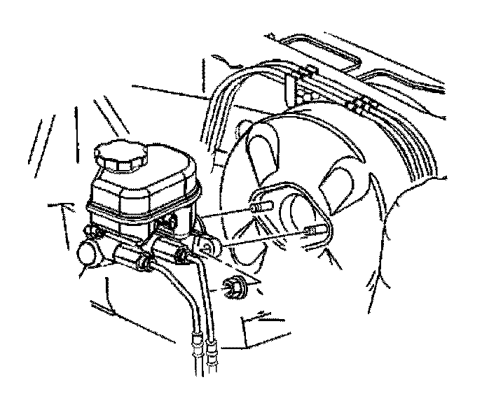
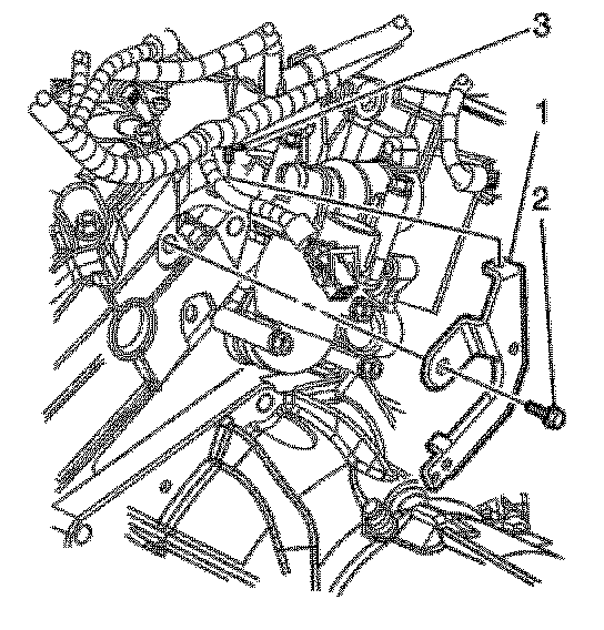
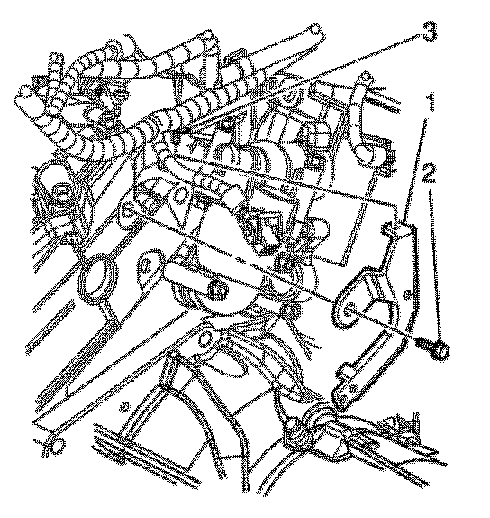
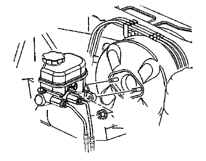
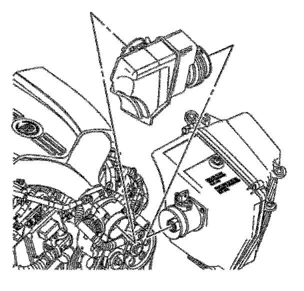
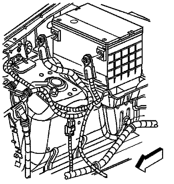
19. Disconnect the purge line (3) from the purge solenoid.
20. Disconnect the fuel pipe (2) from the fuel rail. Refer to: Service and Repair
21. Plug the fuel pipe and cap the fuel rail to prevent fuel loss and/or contamination.
22. Evacuate the air conditioning system. Refer to: Service and Repair
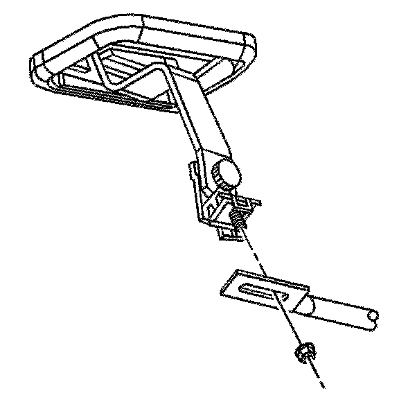
23. Remove the wiper module. Refer to: Service and Repair
Important: Do NOT disconnect the suction hose from the A/C compressor.
24. Disconnect the air conditioning suction hose from the evaporator and remove the suction hose bracket from the shock tower. Refer to: Service and Repair
25. Position and secure suction hose to the engine.
Important: Do NOT disconnect the liquid line from the condenser.
26. Disconnect the air conditioning pressure switch electrical connector and remove the liquid line. Refer to: Service and Repair
27. Remove the radiator support brackets. Refer to: Service and Repair
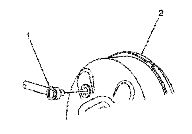
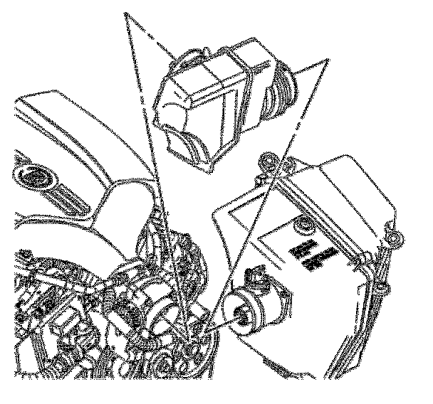
28. Disconnect the brake booster check valve and vacuum hose (1) from the brake booster (2).
29. Position and secure the brake booster hose to the engine.
30. Disconnect the brake fluid level switch electrical connector from the master cylinder.
31. Disconnect the mass air flow sensor electrical connector.
32. Unlock and disconnect the instrument panel (I/P) electrical connector from the engine located at the rear of the left (Bank 2) cylinder head.
33. Position and secure the I/P harness to the vehicle.
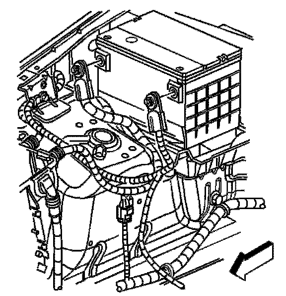
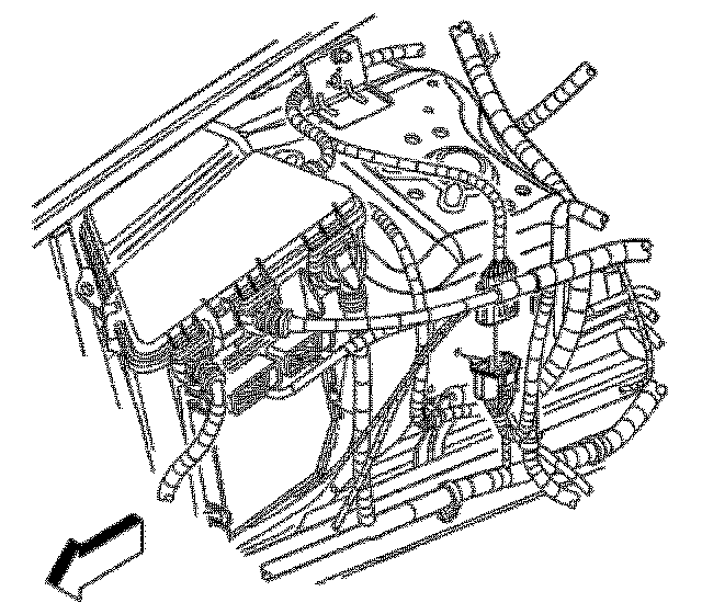
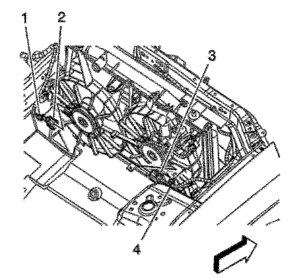
34. Disconnect the engine module wiring harness connectors (1-3) from the underhood electrical center. Refer to: Service and Repair
35. Disconnect the wiring harness from the transmission control module (TCM). Refer to: Service and Repair
36. Remove the ground bolt and wire from the longitudinal rail.
37. Disconnect the engine harness electrical connector at the longitudinal rail.
38. Position and secure the ground wire, engine harness and TCM harness to the engine.
Important: Do NOT disconnect the brake pipes from the master cylinder.
39. Remove the master cylinder nuts.
40. Reposition and secure the master cylinder to the engine.
41. Relieve the fuel system pressure. Refer to: Service and Repair
42. Raise and support the vehicle.
43. Remove the muffler assembly. Refer to: Service and Repair
44. Remove the propeller shaft. Refer to: Service and Repair
45. Remove the air deflector.
Important: DO NOT remove the water bottle.
46. Remove the washer bottle bracket.
47. Disconnect the radiator side air baffles from the radiator.
48. Disconnect the left front brake pipe retainer with the brake pipe from the longitudinal rail.
49. Remove the right front brake pipe from the brake pipe bundle retainer.
50. Disconnect the rear brake pipes (two center pipes) from the brake modulator valve (BPVM). Refer to: Service and Repair
51. Cap and/or plug the brake pipes and the BPMV in order to minimize brake fluid loss.
52. Remove the front tire and wheel assemblies.
53. Remove the intermediate steering shaft. Refer to: Service and Repair
54. Remove the lower engine mount nuts. Refer to: Service and Repair
55. Disconnect the transmission shift linkage from the transmission. Refer to: Service and Repair
56. Disconnect the low oil level sensor electrical connector.
57. Secure the low oil level sensor electrical connector and harness to the engine mount bracket.
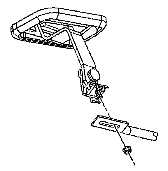
58. Remove the headlamp leveling sensors. Refer to: Service and Repair
59. Secure the shock modules to the lower control arms with a suitable strap in order to prevent damage to the front brake hoses.
60. Remove the right and left shock module upper mounting bolts. Refer to: Suspension
61. Raise the vehicle enough to place a suitable lift table under the engine, transmission, front frame and front suspension assembly.
62. Position a suitable powertrain and/or engine lift table below the frame, engine and transmission.
63. Raise the lift table and/or lower the vehicle to support the frame, engine and transmission.
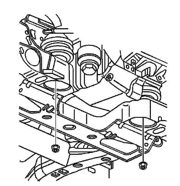
64. Remove the transmission brace to underbody bolts.
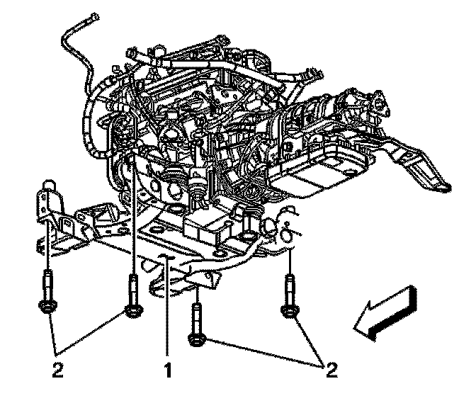
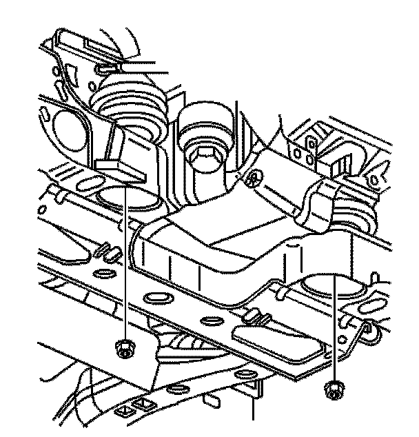
65. Remove the front frame bolts (2).
Important: Ensure that all the hoses, wires, pipes and shock modules clear the vehicle during the removal process.
66. With the aid of an assistant, lower the table and/or raise the vehicle to remove the engine, transmission, front frame and front suspension assembly from the vehicle.
67. Disconnect the ECM upper (chassis side) electrical connector. Refer to: Service and Repair
Important: Do NOT remove the oxygen sensors.
68. Remove the catalytic converters with the oxygen sensors. Refer to: Service and Repair
69. Remove the thermostat housing with the heater pipes, heater hoses and surge tank outlet hose.
70. Remove the starter motor. Refer to: Service and Repair
71. Remove the flywheel bolts.
72. Remove the HO2S connector bracket from the left cylinder head.
73. Remove the engine wiring harness and related components.
74. Disconnect the transmission oil cooler (TOC) pipes from the engine, radiator and the transmission. Refer to: Service and Repair
75. Disconnect the radiator hoses from the water outlet housing and the coolant inlet pipe.
76. Disconnect the power steering cooler hoses from the condenser radiator and fan module (CRFM). Refer to: Service and Repair
77. Cap and plug the power steering hoses and pipes in order to prevent fluid loss and contamination.
78. Remove the CRFM with the radiator hoses from the frame.
79. Install the EN 46114 to the engine.
80. Connect a floor crane to the engine lift brackets and raise the floor crane to partially support the engine.
81. Position a second powertrain lift table below the transmission.
82. Remove the transmission to engine bolts. Refer to: Removal and Replacement
83. Remove the transmission from the engine.
84. Remove the drive belts.Service and Repair
85. Remove the generator and water pump drive belt tensioner.
86. Remove the A/C compressor and power steering drive belt tensioner.
87. Remove the generator and the generator bracket.
88. Remove the air conditioning (A/C) compressor. Refer to: Service and Repair
89. Remove the power steering pump. Refer to: Service and Repair
90. Remove the power steering reservoir from the engine.
91. Remove the oil level indicator.
92. Remove the left exhaust manifold. Refer to: Service and Repair
93. Remove the oil filter adapter.
94. Remove the right exhaust manifold. Refer to: Service and Repair
95. Remove the crankshaft balancer. Refer to: Service and Repair
96. Remove the flywheel. Refer to: Service and Repair
97. Remove the intake manifold. Refer to: Service and Repair
98. Remove the water outlet. Refer to: Service and Repair
99. Remove the block heater.
100. Remove the ECM with the ECM bracket.
101. Use a floor crane in order to remove the engine from the frame.
102. Remove the engine mount brackets with the engine mounts. Refer to: Service and Repair
Installation Procedure
1. Install the engine mount brackets with the engine mounts.
2. Use a floor crane in order to install the engine to the frame.
3. Install the ECM with the ECM bracket.
4. Install the water outlet.
5. Install the block heater.
6. Install the flywheel.
7. Install the intake manifold.
8. Install the crankshaft balancer.
9. Install the right exhaust manifold.
10. Install the oil filter adapter.
11. Install the left exhaust manifold.
12. Install the oil level indicator.
13. Install the generator and the generator bracket.
14. Install the power steering pump.
15. Install the power steering reservoir to the engine.
16. Install the A/C compressor.
17. Install the A/C compressor and power steering drive belt tensioner.
18. Install the generator and water pump drive belt tensioner.
19. Install the drive belts.
20. Install the transmission-to-engine and flywheel-to-torque convertor bolts.
21. Install the starter motor.
22. Remove the EN 46114 from the engine.
23. Install the CRFM with the radiator hoses to the frame.
24. Connect the power steering cooler hoses to the CRFM.
25. Connect the radiator hoses to the water outlet housing and the coolant inlet pipe.
26. Install the transmission oil cooler (TOC) pipes to the engine, radiator and the transmission.
27. Install the engine wiring harness and related components.
28. Install the HO2S connector bracket to the left cylinder head.
29. Install the thermostat housing with the heater pipes, heater hoses and surge tank outlet hose.
30. Install the catalytic converters with the oxygen sensors.
31. Install the fuel lines to the fuel rail and the EVAP purge solenoid.

32. Connect the ECM upper (chassis side) electrical connector.
Important: Ensure that all the hoses, wires, pipes and shock modules clear the vehicle during the installation process.
33. With the aid of an assistant, raise the table and/or lift the vehicle to install the engine, transmission, front frame and front suspension assembly to the vehicle.
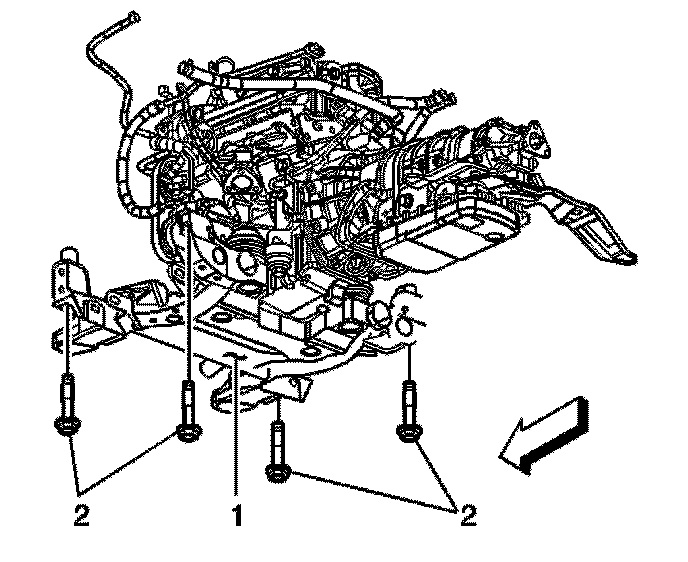
34. Install the front frame bolts (2).
35. Install the transmission support to underbody bolts.
36. Remove the powertrain lift/support table.
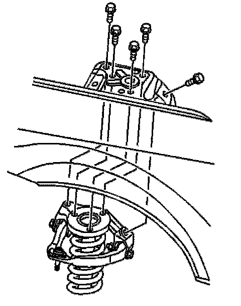
37. Install the right and left shock module upper mounting bolts.
38. Secure the shock modules to the front frame with mechanics wire to avoid stretching the front brake hoses.
39. Install the headlamp leveling sensors.
40. Connect the transmission shift linkage to the transmission.
41. Connect the low oil level sensor electrical connector.
42. Install the lower engine mount nuts.
43. Install the intermediate steering shaft.
44. Install the front tire and wheel assemblies.
45. Install the front brake pipes and retainers to the underbody.
46. Connect the rear brake pipes (two center pipes) to the brake pressure modulator valve (BPVM).
47. Connect the radiator side air baffles to the radiator.
48. Install the washer bottle bracket.
49. Install the air deflector.
50. Install the propeller shaft.
51. Install the muffler assembly.
52. Install the master cylinder.
53. Connect the engine harness electrical connector at the longitudinal rail.
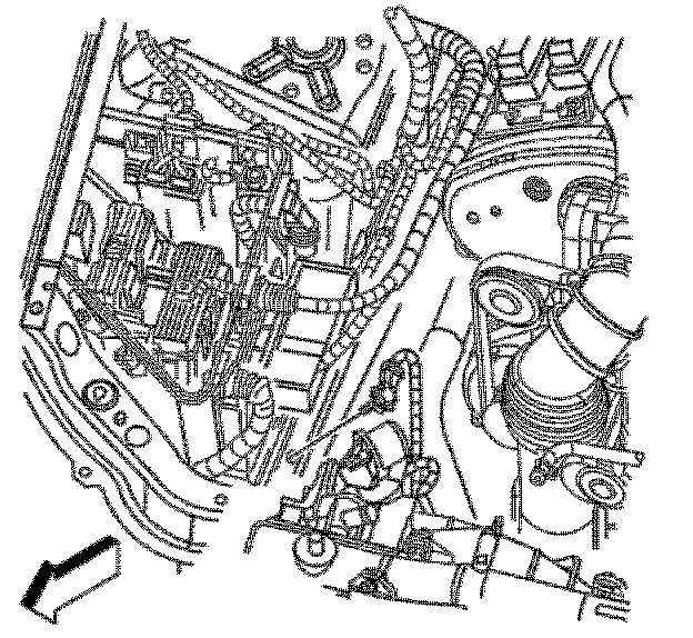
54. Install the ground wire and bolt to the longitudinal rail.
Tighten
Tighten the engine harness ground wire to longitudinal rail bolt to 10 Nm (89 lb in).
55. Connect the wiring harness to the transmission control module (TCM).
56. Connect the engine module wiring harness connectors (1-3) to the underhood electrical center.
57. Connect and lock the instrument panel (I/P) electrical connector to the engine at the rear of the left (Bank 2) cylinder head.
58. Connect the mass air flow sensor electrical connector.
59. Connect the brake fluid level switch electrical connector from the master cylinder.
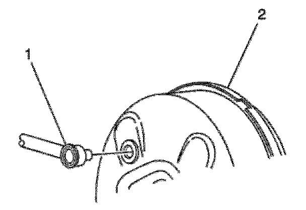
60. Connect the brake booster vacuum hose (1) to the brake booster (2).
61. Install the radiator support brackets.
62. Connect the purge line (3) to the purge solenoid.
63. Connect the fuel pipe (2) to the fuel rail.
64. Connect the heater hoses to the heater core.
65. Install the air inlet duct.
66. Position and secure the surge tank inlet (vent) hose to the vehicle.
67. Connect the surge tank inlet (vent) hose to the water outlet housing and the radiator.
68. Connect the surge tank outlet hose to the surge tank.
69. Connect the air conditioning pressure switch electrical connector and the liquid line to the evaporator.
70. Connect the air conditioning suction hose to the evaporator and install the suction hose bracket to the shock tower.
71. Install the air cleaner duct.
72. Install the cooling fan wiring harnesses (1 and 4) to the fan shroud.
73. Install the cooling fan electrical connectors (2 and 3).
74. Install the wiper module.
75. Install the battery.
76. Install the fuel injector sight shield.
77. Connect the battery positive cable to the battery and the underhood electrical center.
78. Connect the battery negative cable from the battery and the body.
79. Install the J 42640 from the steering column.
80. Fill the cooling system.
81. Charge the air conditioning system.
82. Bleed the brake rear circuits.