Power Liftgate Malfunction
Power Liftgate Malfunction
Diagnostic Instructions
* Perform the Diagnostic System Check - Vehicle (Initial Inspection and Diagnostic Overview) prior to using this diagnostic procedure.
* Review Strategy Based Diagnosis (Initial Inspection and Diagnostic Overview) for an overview of the diagnostic approach.
* Diagnostic Procedure Instructions (Initial Inspection and Diagnostic Overview) provides an overview of each diagnostic category.
Diagnostic Fault Information
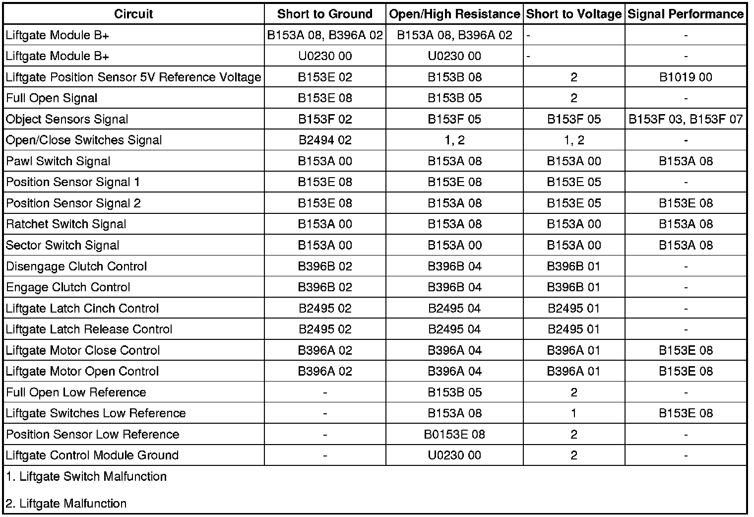
Circuit/System Description
The liftgate module (LGM) controls operation of the liftgate latch motor and the liftgate actuator assembly. Under normal conditions the power latch can only be unlatched under power from the LGM through an input from the liftgate handle switch or the remote keyless entry (RKE) transmitter, but the liftgate may be manually closed to the primary latched position without the LGM performing the power latch function. The liftgate actuator assembly consists of an actuator drive motor that contains 2 internal hall effect sensors. The drive motor is mated to a gear that is connected to an actuator clutch. When the clutch is engaged the motor rotation is transferred to the clutch gear, intermediate gear, and actuator arm gear. The full open switch is a limit switch mounted on the liftgate actuator assembly along side the actuator arm gear, and will make contact with the cam on the actuator arm gear when the liftgate is near the full open position. The LGM continuously monitors the liftgate location and direction of travel using the 2 hall effect sensors located in the drive motor assembly. The sensors are used to determine when the liftgate has reached the full open and full closed points of travel where the actuator clutch should be disengaged. These positions may vary slightly and must be learned when most liftgate components are serviced.
Diagnostic Aids
Power liftgate function will only be allowed if certain operating criteria are met. Any of the following may cause the power liftgate not to function:
* After a power loss of the low current battery supply until the ignition is cycled
* Vehicle is not in park.
* Engine cranking is present.
* Ambient temperature at the LGM must be within -17 to +80°C (+1 to +176°F).
* Liftgate motor excess current is detected.
* System voltage is out of range.
* A DTC is set that disables power liftgate functionality.
* The liftgate is locked when attempting to open from exterior handle.
The LGM also receives input from 2 pressure sensing object detection sensors. If either of these sensors indicates an object may be pinched as the liftgate is brought to the closed position, the liftgate will reverse direction and power close operation will be suspended until the pressure against the sensor is released.
Whenever the LGM loses power or is disconnected, the ignition must be cycled OFF then ON in order to reactivate the LGM.
Certain SIR DTC's will make the power liftgate inoperative. Correct any SIR concern first before performing any extensive power liftgate diagnostics.
Reference Information
Schematic Reference
Liftgate Schematics (Liftgate Schematics)
Connector End View Reference
Component Connector End Views (Connector Views)
Description and Operation
Liftgate Description and Operation (Description and Operation)
Electrical Information Reference
* Circuit Testing (Component Tests and General Diagnostics)
* Connector Repairs (Component Tests and General Diagnostics)
* Testing for Intermittent Conditions and Poor Connections (Component Tests and General Diagnostics)
* Wiring Repairs (Component Tests and General Diagnostics)
Scan Tool Reference
Control Module References (Programming and Relearning) for scan tool information
Circuit/System Verification
1. Ignition ON, observe the Liftgate Handle Sw. Status parameter while pressing and releasing the liftgate handle switch and the liftgate close switch, the parameter should change from Inactive and Active.
• If the parameter does not change, refer to Liftgate Handle Switch Inoperative.
2. Open the liftgate and verify that the liftgate will remain at or near the full open position for several minutes.
• If the liftgate will not remain open, replace the liftgate struts.
3. Command the liftgate to OPEN and CLOSE with a scan tool. The liftgate should OPEN and CLOSE as commanded.
• If the liftgate fails to OPEN, refer to Power Liftgate Inoperative.
• If the liftgate closes and immediately reopens, refer to Liftgate Closes and Reopens.
Circuit/System Testing
Liftgate Handle Switch Inoperative
1. Ignition OFF, disconnect the harness connectors at the liftgate close switch and liftgate handle switch.
2. Ignition ON, verify the scan tool Liftgate Handle Sw. Status parameter is Inactive.
• If not the specified value, test the signal circuit terminal listed below for a short to ground. If the circuit tests normal, replace the LGM.
* Liftgate close switch signal circuit terminal 1
* Liftgate handle switch signal circuit terminal A
3. Install a 3A fused jumper wire between the signal circuit terminal listed below and ground. Verify the scan tool Liftgate Handle Sw. Status parameter is Active.
* Liftgate close switch signal circuit terminal 2
* Liftgate handle switch signal circuit terminal A
• If not the specified value, test the signal circuit for a short to voltage or an open/high resistance. If the circuit tests normal, replace the LGM.
4. Ignition OFF, connect the harness connector at the liftgate handle switch.
5. Ignition ON, observe the scan tool Liftgate Handle Sw. Status parameter while pressing and releasing the liftgate handle switch. The parameter should change between Active and Inactive.
• If the parameter does not change, test or replace the liftgate handle switch.
6. If all circuits test normal, test or replace the liftgate close switch.
Power Liftgate Inoperative
1. Ignition OFF, disconnect the harness connector at the LGM.
2. Ignition ON, verify the scan tool LGM Latch Pawl Sw. parameter is Inactive.
• If not the specified value, test the signal circuit terminal 5 for a short to ground. If the circuit tests normal, replace the LGM.
3. Verify the scan tool LGM Latch Sector Sw. parameter is Inactive.
• If not the specified value, test the signal circuit terminal 4 for a short to ground. If the circuit tests normal, replace the LGM.
4. If all circuits test normal, replace the liftgate latch assembly.
Liftgate Closes and Reopens
Important: Check the alignment of the liftgate striker, if the liftgate striker is adjusted too far inboard it could allow the LGM to detect an excess motor current condition and reverse the motor.
1. Ignition OFF, disconnect the X1 harness connector at the LGM.
2. Test for infinite resistance between the signal circuit terminal 8 and ground.
• If less than the specified value, test the signal circuit for a short to ground.
3. Test for 15k - 25k ohms between the signal circuit terminal 8 and the low reference circuit terminal 16.
• If not within the specified range, test the signal circuit between the left and right liftgate object sensors and the low reference circuit for an open/high resistance. If the circuits test normal, test or replace the left or right liftgate object sensor.
4. If all circuits test normal, replace the LGM.
Component Testing
Liftgate Handle Switch
1. Ignition OFF, disconnect the harness connector at the liftgate handle switch.
2. Test for infinite resistance between the signal terminal A and the low reference terminal B with the switch in the open position.
• If less than the specified value, replace the liftgate handle switch.
3. Test for less than 1 ohm between the signal terminal A and the low reference terminal B with the switch in the closed position.
• If greater than the specified range, replace the liftgate handle switch.
Liftgate Close Switch
1. Ignition OFF, disconnect the harness connector at the liftgate handle switch.
2. Test for infinite resistance between the signal terminal 1 and the low reference terminal 2 with the switch in the open position.
• If less than the specified value, replace the liftgate close switch.
3. Test for less than 1 ohm between the signal terminal 1 and the low reference terminal 2 with the switch in the closed position.
• If greater than the specified range, replace the liftgate close switch.
Repair Instructions
Perform the Diagnostic Repair Verification (Verification Tests) after completing the diagnostic procedure.
* Liftgate Outside Handle Replacement (Service and Repair)
* Liftgate Actuator Switch Replacement (Service and Repair)
* Liftgate Side Upper Sensor Replacement (Service and Repair)
* Control Module References (Programming and Relearning) for LGM replacement, setup, and programming