Service Procedure
INSPECTION1. BLOCK THE WHEELS AND APPLY THE PARKING BRAKE. Lift the hood and listen for an audible exhaust noise while increasing the engine speed in park.
2. A check for a leaking exhaust seal (donut) should be performed prior to exhaust manifold replacement. If the seal leaks, replace it and rerun the inspection (WITH THE WHEELS BLOCKED AND PARKING BRAKE APPLIED) before exhaust manifold replacement.
MANIFOLD REPLACEMENT
IMPORTANT
The oxygen sensor uses a permanently attached pigtail and connector. This pigtail should not be removed from the oxygen sensor. Damage or removal of the pigtail or connector could affect proper operation of the sensor.
Take care when handling the oxygen sensor. The in-line electrical connector and louvered end must be kept free of grease, dirt or other contaminants. Also, avoid using cleaning solvents of any type. Do not drop or roughly handle the sensor.
1. Disconnect battery ground cable from battery.
2. Disconnect Oxygen sensor electrical connector.
3. Carefully remove Oxygen sensor from exhaust manifold.
4. Remove engine oil dipstick.
5. Remove air cleaner hot air duct hose.
6. Remove the screw retaining the dipstick tube bracket (and A/C suction line bracket, if so equipped).
7. Loosen the generator support to generator bolt, remove the two generator bracket to generator bolts, being careful not to loosen the spacer used at the left generator to bracket bolt.
8. Remove the generator belt from the generator pulley, rotate the generator upward and install the left generator to bracket bolt loosely so that it acts as a stop against the bracket preventing the generator from rotating too far downward.
9. Raise the vehicle.
10. Disconnect the exhaust pipe from the exhaust manifold.
11. Lower the vehicle.
12. Remove exhaust manifold to cylinder head bolts, lift the exhaust manifold off the exhaust pipe flange and remove the exhaust manifold from the cylinder head.
13. Clean all mating surfaces, bolts and bolt holes.
14. Reverse the manifold removal procedure and torque the fasteners to the following specifications:
Exhaust manifold bolt: 46-60 N-m (34-44 Lb. Ft.) Generator Brkt. to Head: 40-60 N-m (29-44 Lb. Ft.)
Generator Brace: 40-60 N-m (29-44 Lb. Ft.)
Generator Pivot Bolt: 40-60 N-m (29-44 Lb. Ft.)
Generator Adjustment Bolt: 20-27 N-m. (15-20 Lb. Ft.)
IMPORTANT
New or service sensors will already have a special anti-seize compound on the threads. If a sensor is removed from an engine, and if it is reinstalled, the threads must have anti-seize compound applied before reinstallation.
15. Coat threads of oxygen sensor with anti-seize compound P/N 5613695 or equivalent if necessary.
16. Reinstall sensor in manifold, torque to 41 N-m. (30 Lb. Ft.).
17. Reconnect sensor electrical connector.
18. Connect battery ground cable to the battery.
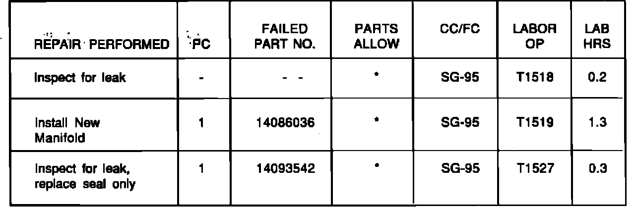
CLAIM INFORMATION
Submit a Claim with the information indicated below for those vehicles beyond 5 years/ 50,000 miles; use the applicable Warranty labor operation number for those vehicles within 5 years/50,000 miles:
* The "Parts Allowance" should be the sum total of the current GMSPO Dealer Net price plus 30% of all parts required for the repair.
Refer to the Chevrolet Claims Processing Manual for details on Claim Submission.