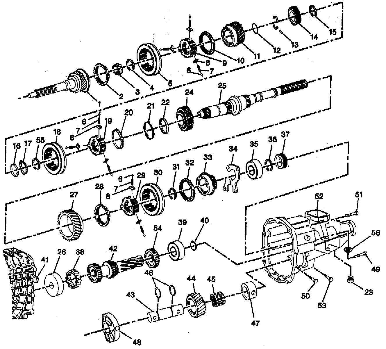
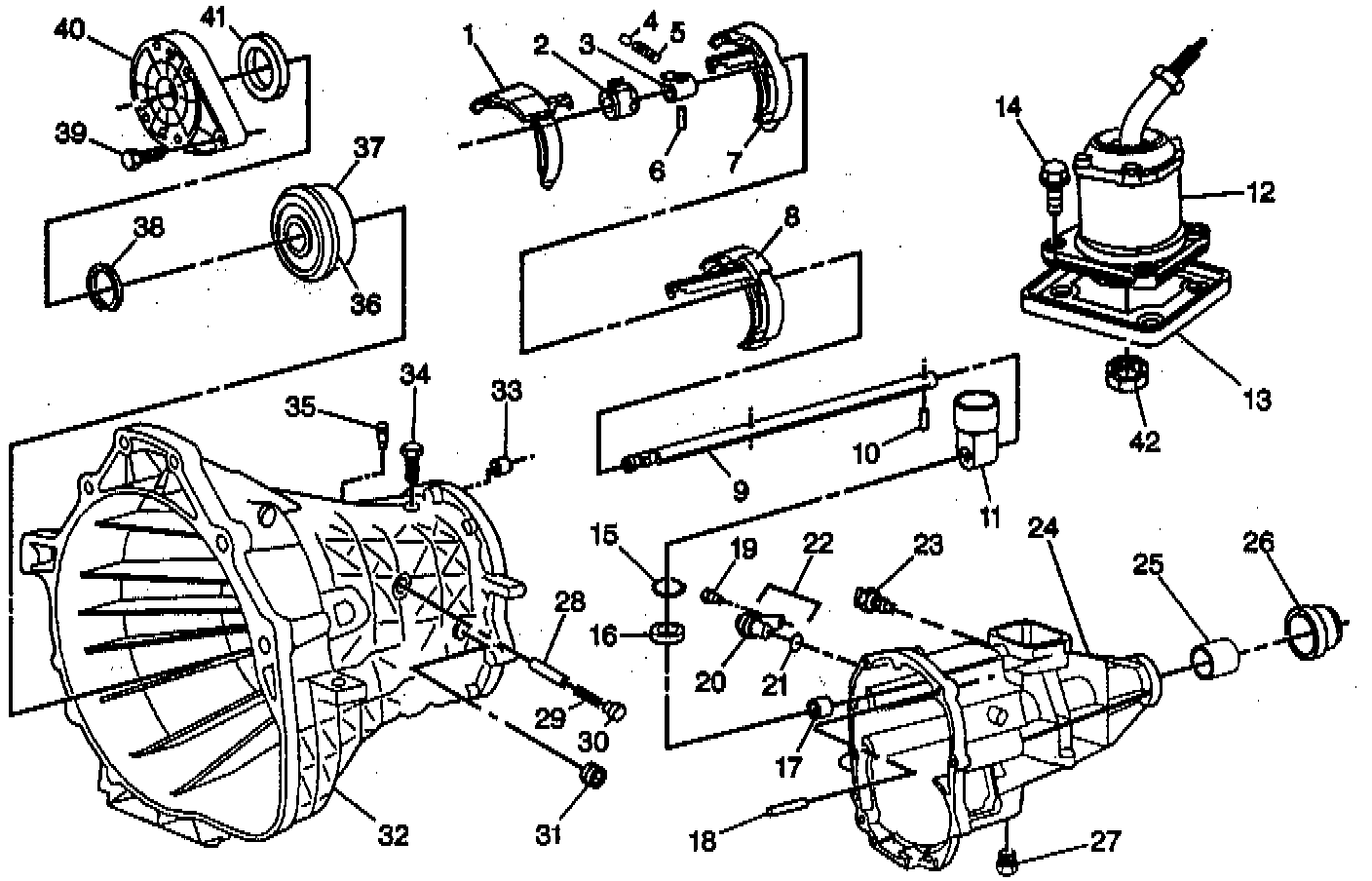
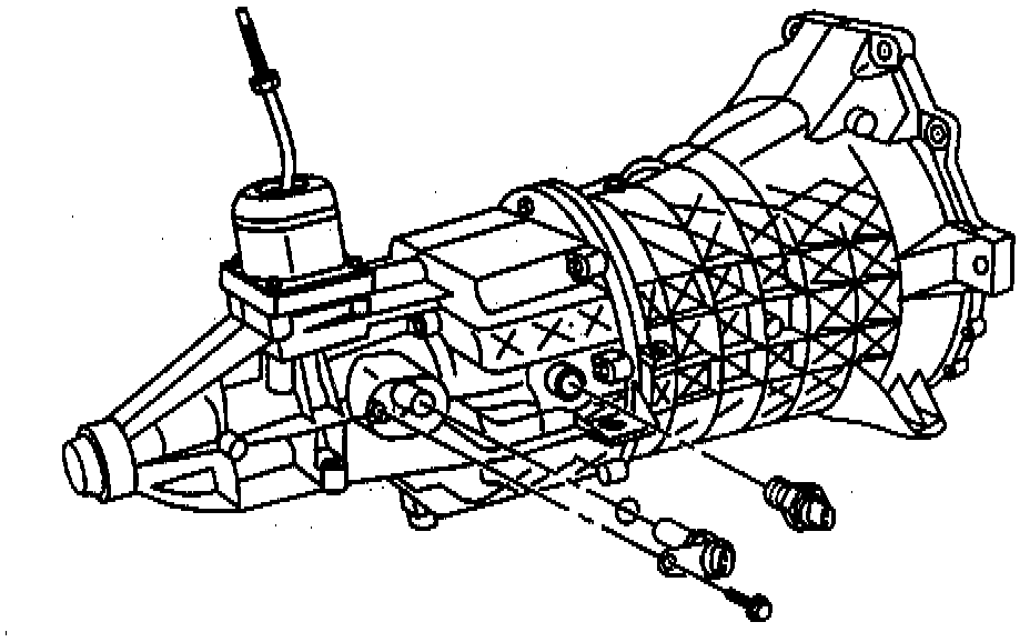
N. Transmission Assembly
- Tools Required:- J 22873 Slide Hammer
- J 41663 Main Shaft Adapter Assembly Pallet
- J 36183 Input Shaft Press Tube With Cap
- J 36184 Input Shaft Press Tube Reducer
NOTICE: All synchronizer blocking rings found inside the transmission are Interchangeable except those used on the reverse synchronizer.
Important:
- The Synchronizer sleeves must be assembled with the offset teeth toward the second, third, and fifth gear. Additional sleeve identification is as follows:
- First and second: one groove on the outer diameter (OD) of the first gear.
- Third and forth: two grooves on the OD of the third gear.
- Fifth and reverse: two grooves on the OD of the fifth gear, one groove on the reverse gear.
- Lubricate all components during the assembly process. Use lubricant Synchromesh Transmission Fluid with friction modifier GM P/N 12377916 or equivalent.
INSTALL OR CONNECT
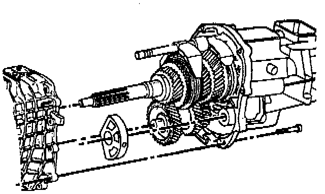
1. Position the following onto the output end of the main shaft:
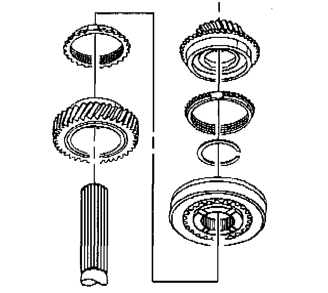
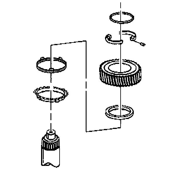
A. Reverse gear.
B. Synchronizer blocking ring.
C. Fifth reverse synchronizer with J 22873.
D. Synchronizer blocking ring.
E. Snap ring.
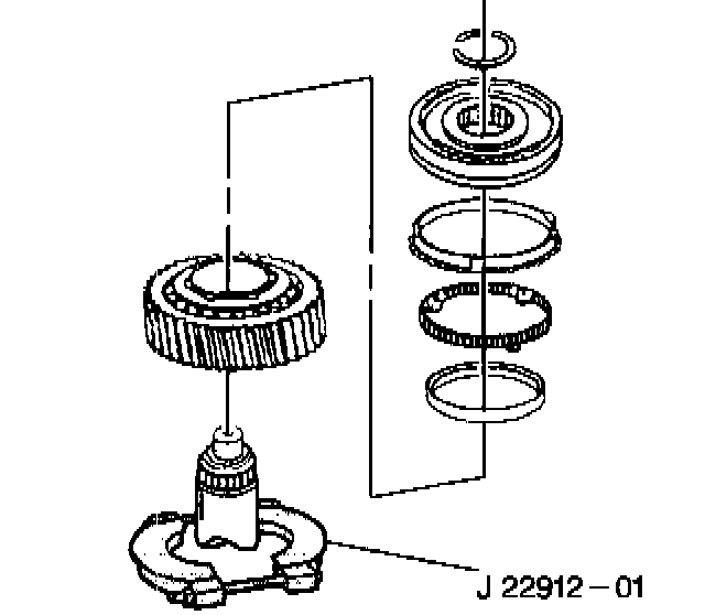
F. Fifth gear.
G. Ball bearing with J 22873.
H. Snap ring.
Part 1 Of 2:
Part 2 Of 2:
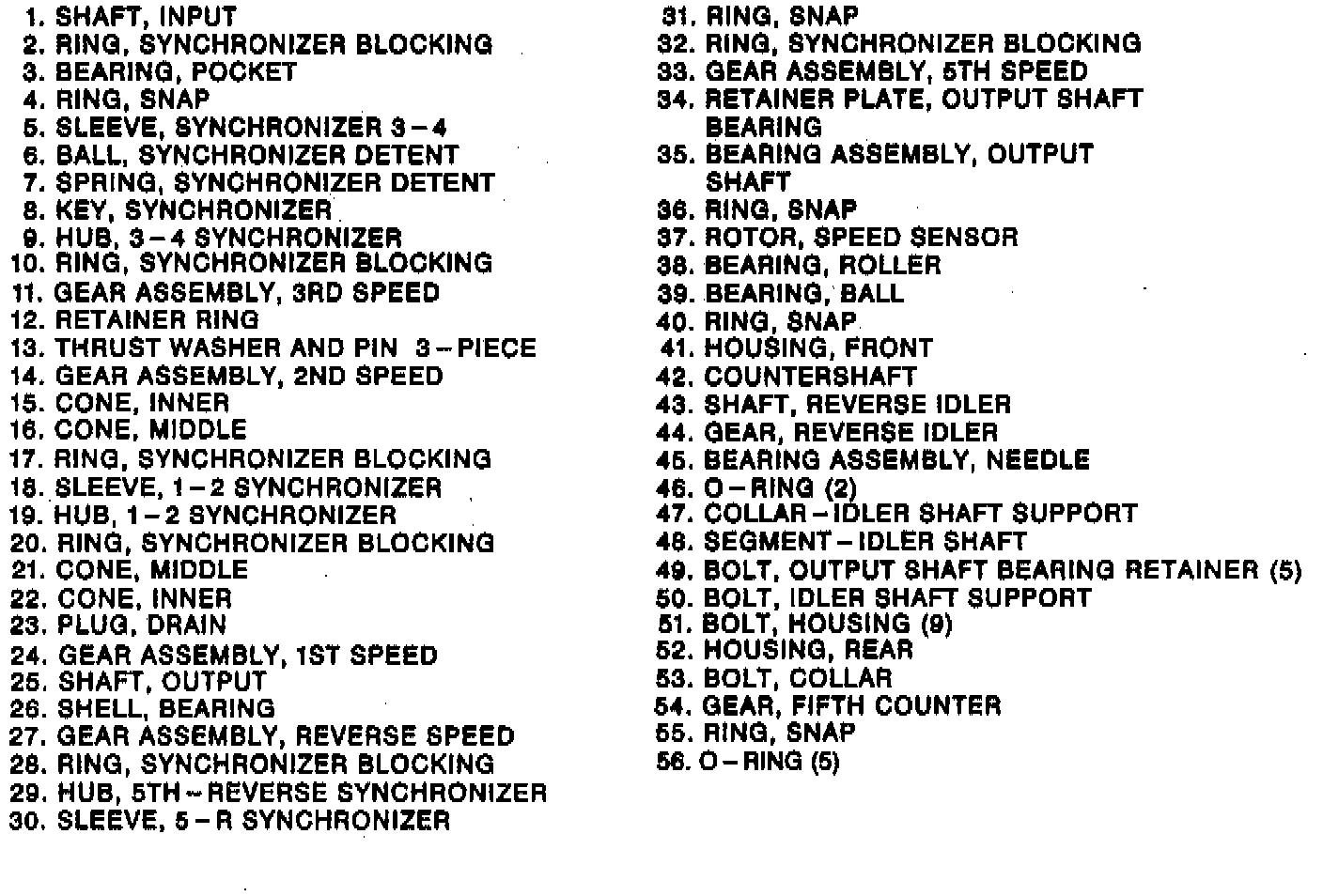
I. New speed sensor gear (rotor) with J 22873.
- Position the speed sensor gear down the main shaft two inches from the ball bearing.
2. Position the following onto the input end of the main shaft:
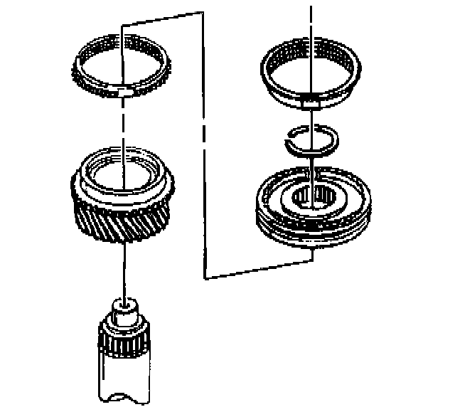
A. First gear.
B. Inner cone.
C. Middle cone.
- Ensure that the scribed hub is aligned properly.
D. Two synchronizer blocking rings and first and second gear synchronizer and hub with J 22873.
- Align the synchronizer rings (one on each side of the synchronizer and hub) with the keys on the first and second gear synchronizer.
E. Snap Ring.
- Position the snap ring into the slot on the main shaft.
F. Middle cone.
G. Inner cone.
H. Second gear.
I. Two piece split washer and pin with retainer ring.
J. Third gear.
K. Two synchronizer blocking rings and third and fourth gear synchronizer and hub with J 22873.
- Align the synchronizer blocking rings (one on each side of the synchronizer and hub) with the keys on the third and fourth gear synchronizer.
L. Snap ring.
M. Pocket bearing.
N. Input shaft.
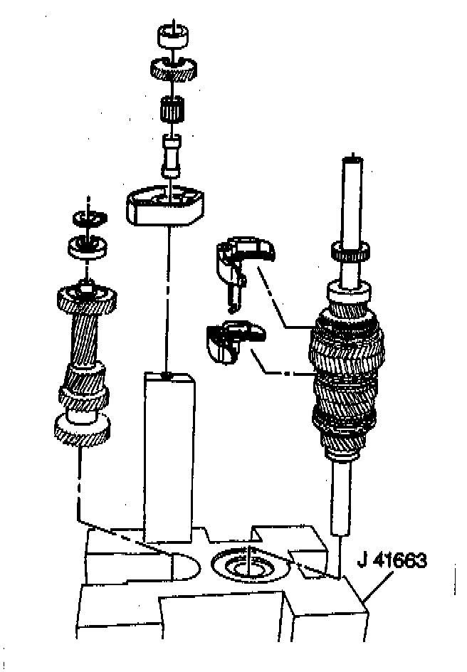
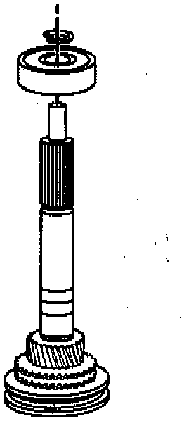
3. Flip (turn over) the main shaft and reposition it onto J 41663 with the input shaft down.
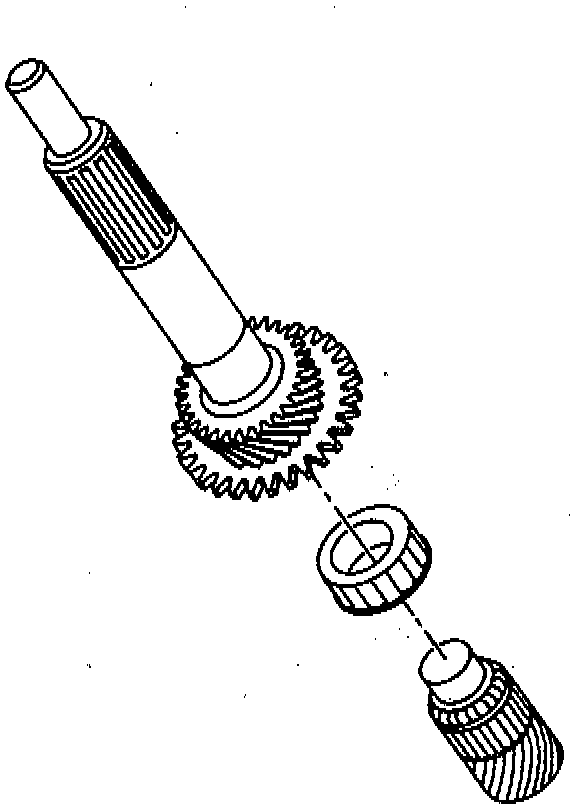
4. Press the counter shaft rear bearing onto the counter shaft.
5. Snap ring on to the counter shaft.
6. Position the counter shaft onto J 41663.
7. Position the following onto the reverse idler shaft:
- Ensure the chamfer on the segment and collar are facing up toward the rear of the transmission when assembling the reverse idler gear.
- Ensure that the groove on the idler gear is toward the collar.
A. Two O-rings onto the idler reverse shaft.
B. Caged roller bearing.
C. Reverse idler gear.
D. Idler shaft support collar.
8. Reverse idler shaft assembly onto J 41663.
9. Output shaft bearing retainer onto the mainshaft and countershaft.
- Ensure that the output shaft bearing retainer is positioned behind the ball bearings on the mainshaft and countershaft.
- Ensure that the (fork) end of the output shaft bearing retainer is positioned under the counter shaft ball bearing.
- Ensure that the hook end of the output shaft bearing retainer is positioned under the main shaft ball bearing.
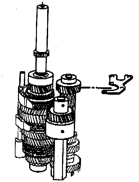
10. Fifth/reverse shift fork onto the first/second shift fork.
11. Fork assemblies onto the first/second and fifth/reverse gear sleeves.
12. Rear housing over the mainshaft, countershaft, and reverse idler shaft assembly.
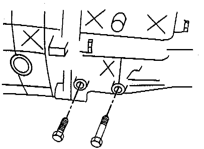
13. Two bolts securing the reverse idler shaft assembly to the rear housing.
- Two different length bolts are used to secure the idler shaft segment to the rear housing. The forward (front) reverse idler shaft assembly hole houses the short bolt.
14. Tighten the two idler shaft segment to the rear housing bolts finger tight.
Important:
- Ensure the five O-rings used with the five output shaft bearing retainer to housing bolts in Step 14, are "New" O-rings.
- Position the five "New" O-rings under the heads of the five output shaft bearing retainer to housing bolts prior to bolt installation.
- Five bolts and O-rings securing the rear housing to the output shaft bearing retainer.
Important:
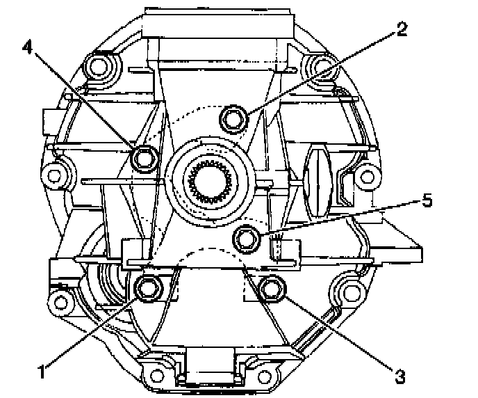
- When installing the five output shaft bearing retainer to housing bolts, finger start bolts 1, 2, and 4 first, then finger start bolts 3 and 5.
- Finger tighten the five output shaft bearing retainer to housing bolts in the order 1, 2, 4, 3, and 5.
- Tighten the five output shaft bearing retainer to housing bolts to 22 Nm (16 ft. lbs.) in the order 1 through 5.
- Re-tighten the five output shaft bearing retainer to housing bolts to 22 Nm (16 ft. lbs.) in the order 1 through 5.
Tighten
- The five output shaft bearing retainer to housing bolts to 22 Nm (16 ft. lbs.) two times.
- The reverse idler shaft assembly to housing rear bolt to 22 Nm (16 ft. lbs.).
- The reverse idler shaft assembly to housing forward bolt to 44 Nm (33 ft. lbs.).
15. Remove the rear housing assembly from J 41633 and place it horizontally.

16. Third/forth fork onto the third and forth gear synchronizer sleeve.
17. Shift shaft, shift shaft bushing, shift shaft lever, and shift shaft socket into the rear housing.
- Shift shaft through the third/fourth gear fork, shift shaft bushing, shift shaft lever, first/second shift fork, fifth/reverse shift fork, and into the rear housing.
- Push the shift shaft down when installing into the rear housing.
18. Shift shaft lever roll pin (22 mm) into the shift shaft lever.
- Install the roll pin to set flush with the shift shaft lever assembly.
19. Shift shaft socket and roll pin (30 mm) onto the shift shaft.
- Ensure that the shift shaft socket roll pin is flush with the shift shaft socket hole.
20. Shift shaft spring and plunger assembly into the shift shaft lever assembly.
21. Position the transmission into the third gear.
- The transmission can be positioned into third gear by centering the shift shaft and pushing the shift shaft all the way to the rear of the rear housing.
22. Apply Loctite 518 sealant to the mating surfaces of the rear housing.
Part 1 Of 2:
Part 2 Of 2:
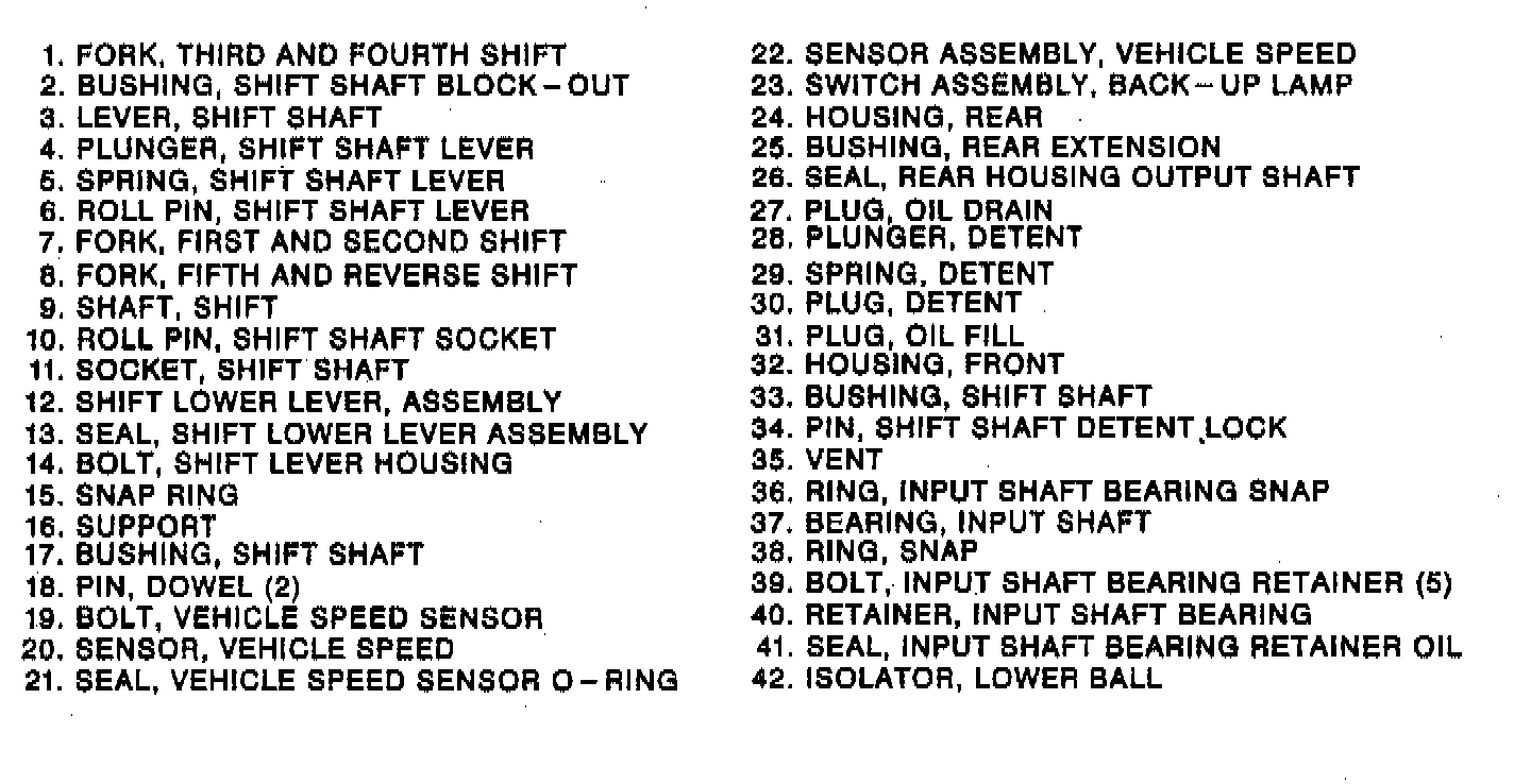
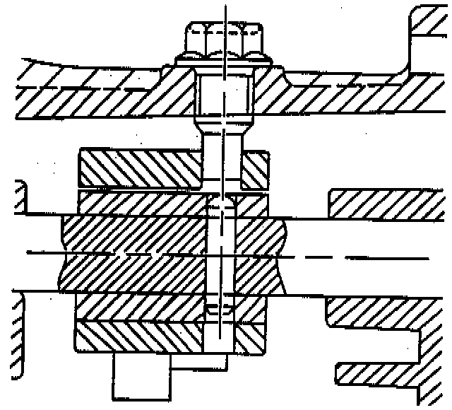
23. Input shaft ball bearing into the front housing using J 36183 and J 36184.
24. Front counter shaft roller bearing into the front housing with petrolatum.
- Ensure that the small end of the counter shaft bearing is toward the front housing.
25. Front housing onto the rear housing.
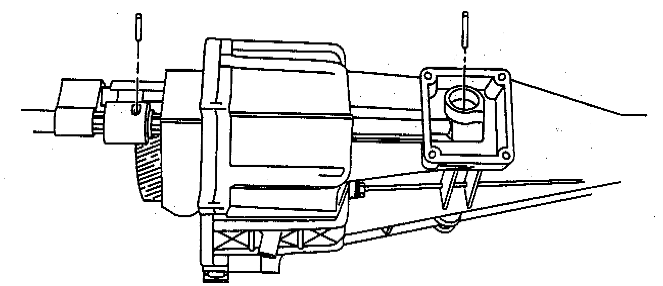
26. Shift shaft detent blackout bushing pin into the top of the front housing.
- Install the shift shaft detent blackout bushing pin by hand to ensure that the detent lock pin installs into the shift shaft lever and shift shaft bushing.
27. Nine bolts securing the front 'housing to the rear housing.
- Tighten:
- Nine housing bolts to 33 Nm (24 ft. lbs.).
- The shift shaft detent blackout bushing pin to 33 Nm (24 ft. lbs.).
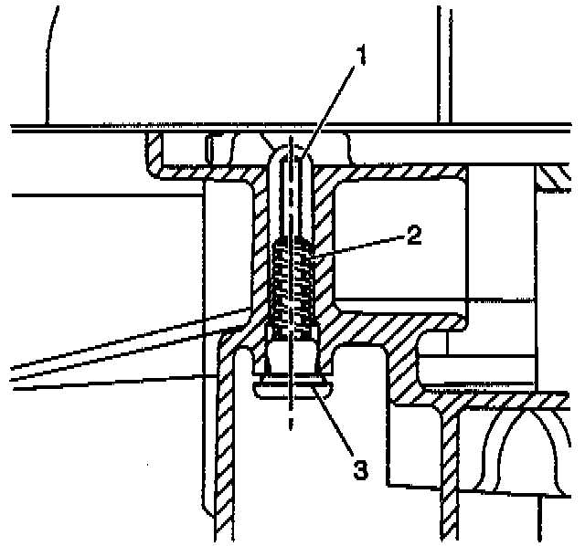
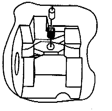
28. Shift shaft detent plunger (1), spring (2), and detent plug (3).
29. Snap ring on the input shaft front ball bearing.
30. Input shaft bearing retainer to the front housing.
- Apply RTV sealant to the mating surfaces of the input shaft bearing retainer prior to installation.
31. Five bolts securing the input shaft bearing retainer to the front housing.
- Tighten bolts securing the input bearing retainer to 29 Nm (21 ft. lbs.).
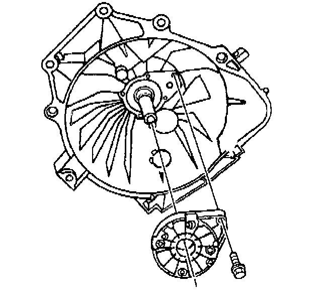
32. Backup light switch into the rear housing.
- Tighten backup light switch to 37 Nm (28 ft. lbs.).
33. Add transmission oil. Refer to SPECIFICATIONS.

34. Oil fill plug using J 36511.
- Tighten oil fill plug to 23 Nm (17 ft. lbs.).
Important: During the installation of the shift tower, the transmission must be in the 3rd or 4th gear position. After installing the shift tower to the transmission, the shifter can be engaged into other shift positions.