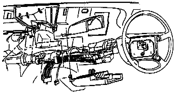
Multifunction Turn Signal/Hazard Switch Replacement
REMOVE OR DISCONNECT1. Make sure the lever is in the center or "OFF" position.
2. Negative battery cable.
WARNING: This vehicle is equipped with Supplemental Inflatable Restraint (SIR). Refer to WARNINGS in "Service Precautions".
3. Disable the SIR system.
Disconnecting The Inflator Module From The Steering Wheel:

4. Inflator module.
Horn Contact Replacement:

5. Horn plunger contact.
Steering Wheel Replacement:

6. Steering wheel nut.
Steering Wheel Removal:

7. Steering wheel using J 1859-A.
8. Two torx(r) screws from lower column cover.
- Tilt cover down and slide back to disengage locking tabs.
9. Lower column cover.
10. Two torx(r) head screws from upper column cover.
11. Ignition lock assembly from upper column cover.
Steering Column Cover Assembly:
12. Upper column cover.
13. Wire harness strap.
14. Two wire harness straps from steering column wire harness.
15. Steering column wire harness from I/P wire harness.
16. Gray and black connectors of switch from column connector.
17. Two torx(r) screws.
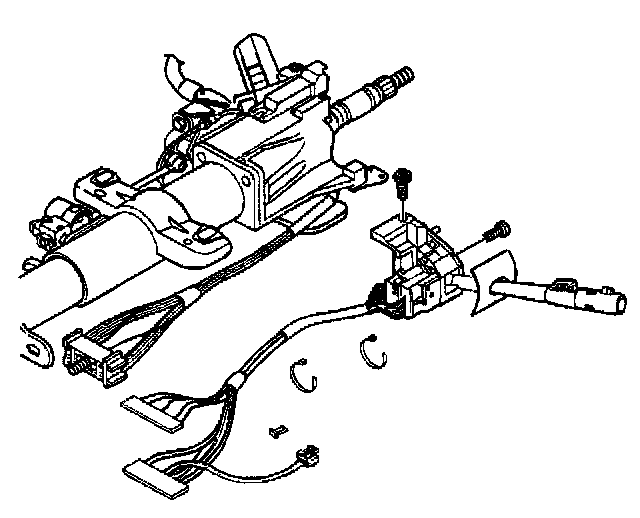
18. Multifunction turn signal/hazard switch assembly.
INSTALL OR CONNECT
1. Multifunction turn signal/hazard switch assembly.
- Use small blade screwdriver to compress electrical contact and move multifunction switch into position.
- Electrical contact must rest on canceling cam assembly.
2. Two torx(r) screws.
Tighten to 6 Nm (53 lb in).
3. Gray and black connectors of switch to steering column connector.
4. Steering column connector to I/P wire harness.
5. Two wire harness straps to steering column wire harness.
6. Wire harness strap.
7. Upper column cover.
8. Ignition lock assembly to upper column cover.
9. Two torx(r) head screws to upper column cover.
Tighten to 1.4 Nm (12 lb in).
10. Lower column cover.
11. Two torx(r) head screws to lower column cover.
Tighten to 6 Nm (53 lb in).
12. Make sure the lever is in the center or "OFF" position.
13. Steering wheel onto the steering shaft.
14. Steering wheel nut.
Tighten to 41 Nm (30 lb ft).
15. Horn plunger contact.
16. Inflator module.
17. Negative battery cable.
18. Enable the SIR system.