Ignition Relay Diagnosis
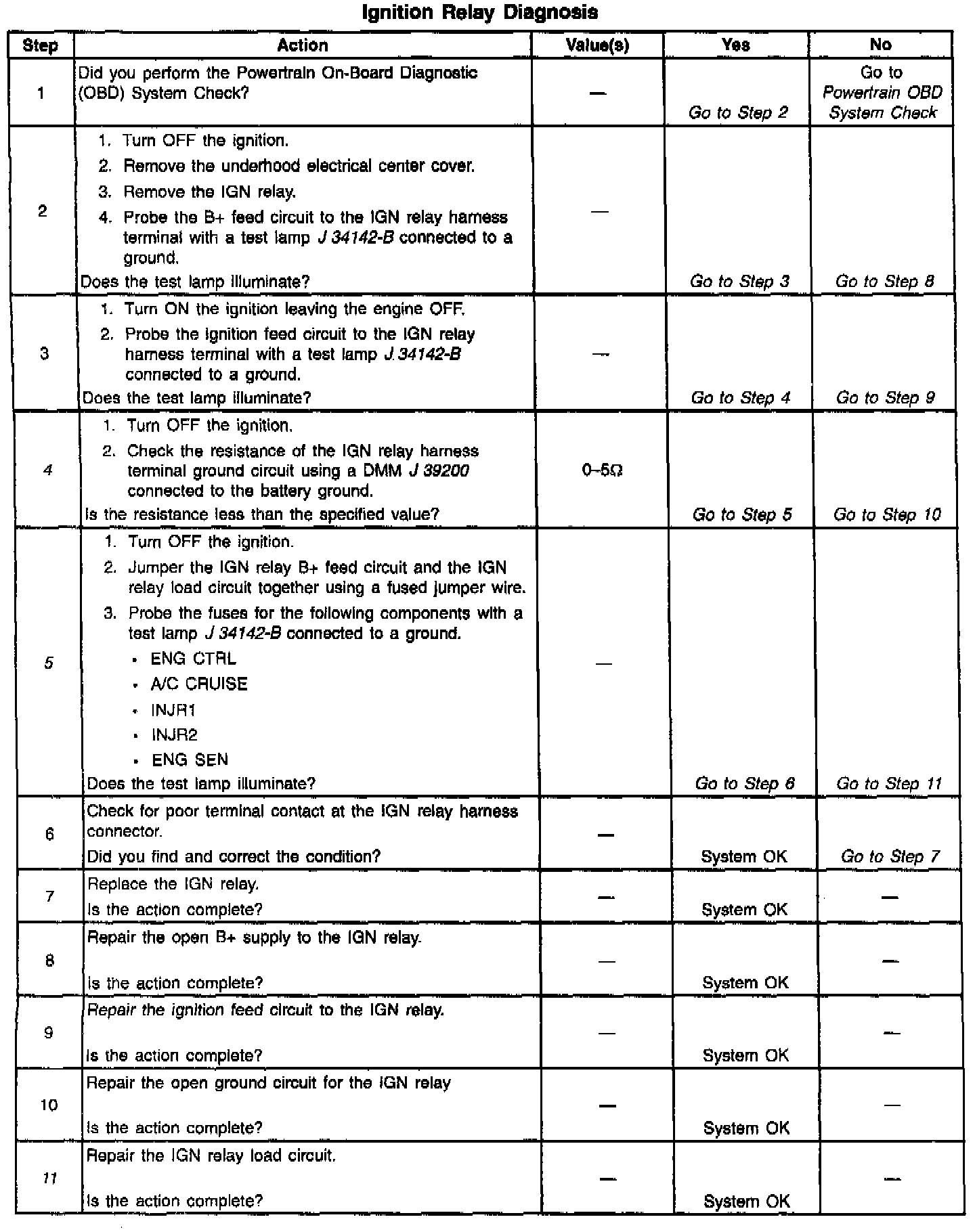
Diagnostic Chart:
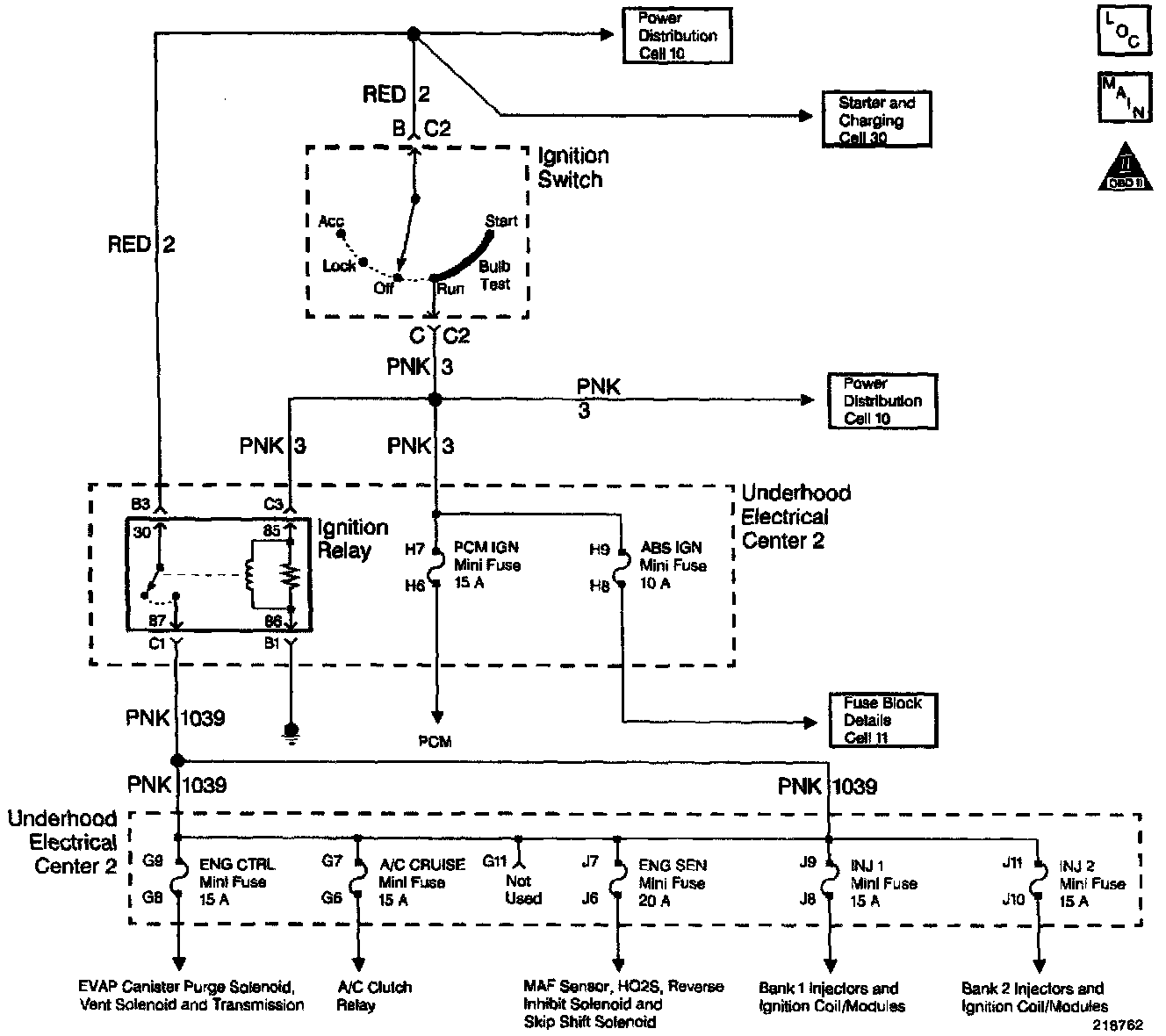
Wiring Diagram:
CIRCUIT DESCRIPTION
The IGN relay protects the battery from a parasitic draw. The following components are powered by the IGN relay:
- Injectors/Ignition coils.
- Transmission.
- A/C system.
- [1][2]EVAP solenoid and EVAP Vent Valve.
- MAF sensor.
- Heated Oxygen Sensors.
DIAGNOSTIC AIDS
The following may cause an intermittent:
- Poor connections. Check for adequate terminal tension. Refer to Troubleshooting Procedures, Checking Terminal Contact (Electrical Diagnosis/Repair Procedures) for proper procedure.
- Corrosion.
- Mis-routed harness.
- Rubbed through wire insulation.
- Broken wire inside the insulation.
TEST DESCRIPTION
The numbers below refer to the step numbers on the diagnostic table.
4. For any test that requires probing the PCM or a component harness connector, use the Connector Test Adapter Kit J 35616-A. Using this kit prevents damage to the harness connector terminals.
5. This step isolates the circuit from the IGN relay. All of the circuits at the relay are good if the test lamp illuminates.
9. The open circuit will be between the splice and the IGN relay.
11. Remove the underhood electrical center and inspect the circuits that are supplied a voltage by the IGN relay.