ETS Off Indicator OFF No DTCS Set
ETS Off Indicator Off No DTCs Set Wiring Diagram:
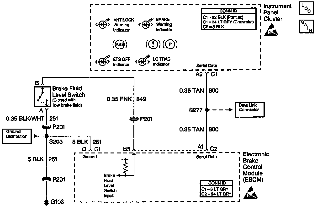
ETS Off Indicator Off No DTCs Set:
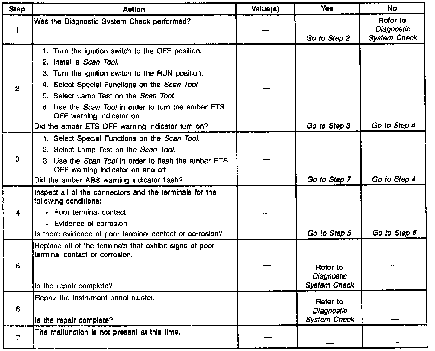
CIRCUIT DESCRIPTION
Two-way serial communication is sent back and forth between the EBCM\A and the IPC. A message from the IPC is sent to the EBCM within seven seconds after ABS initialization. A serial communication failure does not allow the proper warning indicator commands to be sent back to the IPC.
DIAGNOSTIC AIDS
The scan tool Serial Data Link (SDL) monitor used in this diagnostic is within the body portion of the scan tool. This requires exiting from the chassis portion of the scan tool to the main menu and entering into the body portion of the scan tool menu and selecting SDL MONITOR.
With the SDL monitor (ABS to IPC mode), any message that is being transmitted on the serial data link can be observed. Refer to Instrument Panel luster for further serial data link information. The frequency of the malfunction can be checked by using the ENHANCED DIAGNOSTIC function of the scan tool, as described in "Enhanced Diagnostics".
The following conditions may cause an intermittent malfunction:
^ A poor connection
^ Rubbed-through wire insulation
^ A broken wire inside the insulation
Use the Lamp Test function of the Scan Tool in order to turn the indicator on while looking for an intermittent malfunction in the ETS OFF warning indicator circuitry.
Thoroughly inspect any circuitry that may cause the intermittent complaint for the following conditions:
^ Backed out terminals
^ Improper mating
^ Broken locks
^ Improperly formed or damaged terminals
^ Poor terminal-to-wiring connections
^ Physical damage to the wiring harness
IMPORTANT: Zero the J 39200 test leads before making any resistance measurements. Refer to the J 39200 user's manual.