Intake Manifold: Service and Repair
REMOVAL PROCEDURE^ Tools Required
- J34730-1A Fuel Pressure Gauge
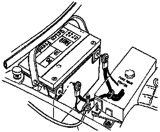
1. Disconnect the negative battery cable.
2. Raise the vehicle and support.
3. Drain the cooling system.
4. Lower the vehicle.
5. Disconnect the Intake Air Temperature (IAT) sensor connector.
6. Disconnect the Mass Air Flow (MAF) sensor connector.
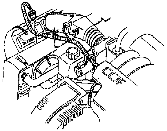
7. Disconnect the fuel pressure regulator purge tube from the air intake duct.
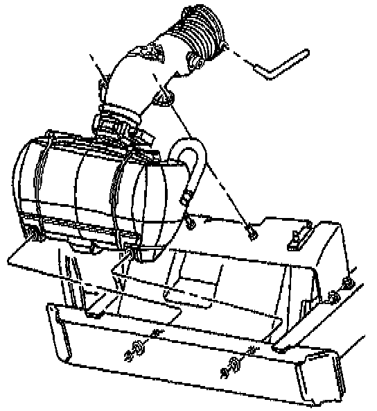
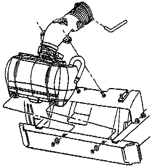
8. Remove the air intake duct and air cleaner assembly.
9. Remove the engine beauty covers.
10. Relieve the fuel system pressure using J 34730-1A.
IMPORTANT: Cap the fittings and plug the holes when separating the fuel system components this prevents the dripping of fuel and eliminates dirt and other contaminants from entering the fuel system.
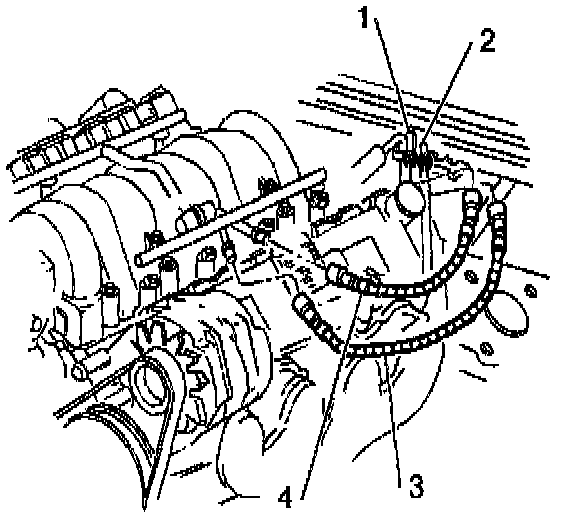
11. Disconnect the fuel lines (3 and 4) from the fuel rail.
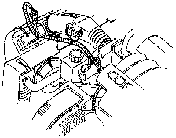
12. Remove the vacuum and crankcase vent hoses.
13. Remove the throttle body coolant outlet hose from the throttle body.
14. Disconnect the fuel injector connectors.
15. Disconnect all the remaining electrical connections from the intake manifold.
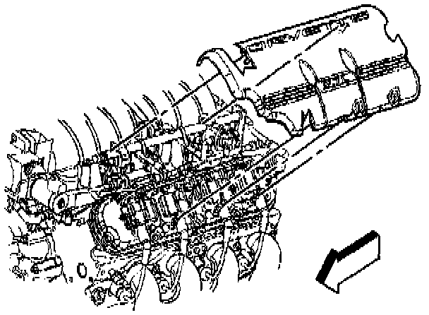
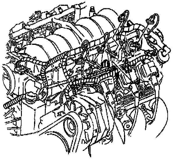
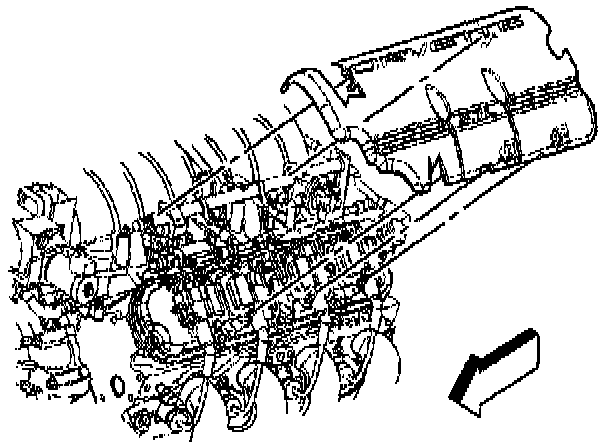
16. Remove the intake manifold.
INSTALLATION PROCEDURE
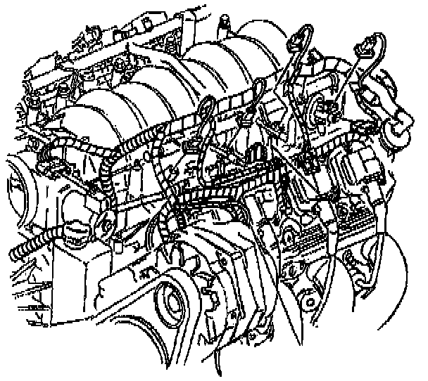
1. Install the intake manifold.
2. Connect the fuel injector wire harness connectors.
3. Connect all remaining electrical connections to the intake manifold.
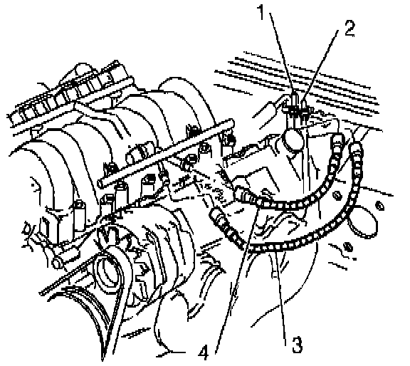
4. Install the fuel lines (3 and 4) to the fuel rail.
5. Install the engine beauty covers.
6. Install the air intake duct and air cleaner assembly.
7. Connect the fuel pressure regulator purge tube to the air intake duct.
8. Connect the MAP sensor connector.
9. Connect the IAT sensor connector.
10. Fill the cooling system.
11. Connect the negative battery cable.
^ Tighten the negative battery cable bolt to 15 Nm (11 ft. lbs.).
12. Program the Transmitters.