Pinion Depth Adjustment
^ Tools Required- J 42168-1 Gauge Cylinder
- J 42168-2 Gauge Block
- J 42168-9 Strap
- J 42168-12 Plug
- J 42170 Bearing Race Installer
- J 42172 Bearing Race Installer
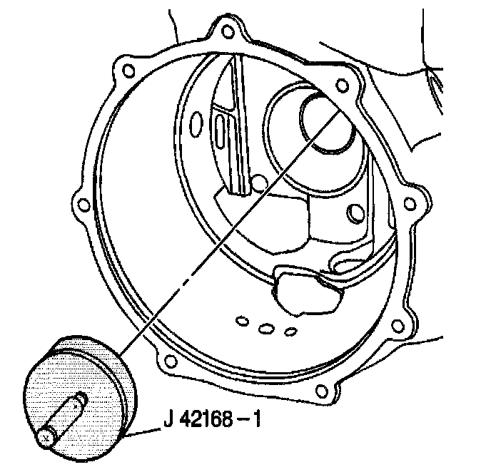
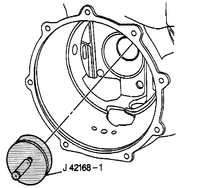
1. Install the J 42168-1 into the left side bearing race bore of the differential housing.
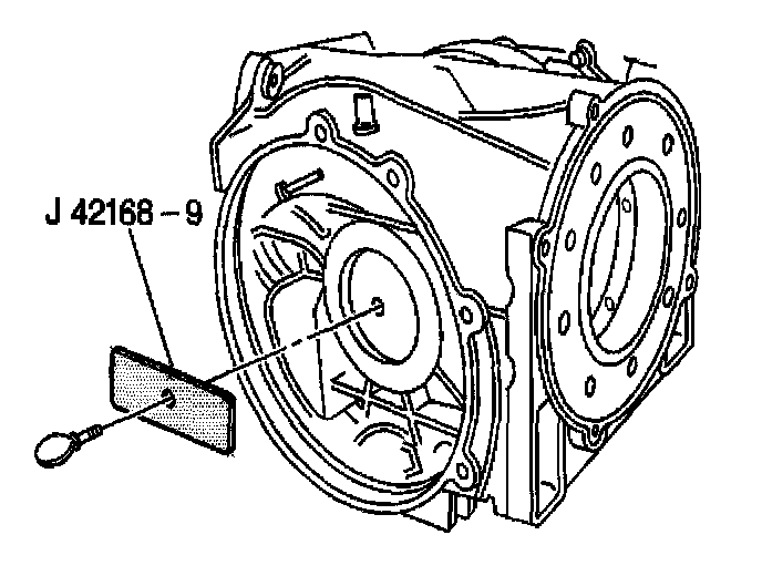
2. Install the J 42168-9 and thumbscrew to the J 42168-1.
3. Tighten the thumbscrew until snug.
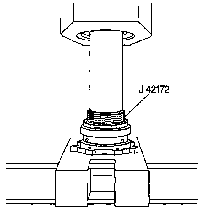
4. Install the drive pinion front bearing inner race into the drive pinion housing using the J 42172 and a hydraulic press.
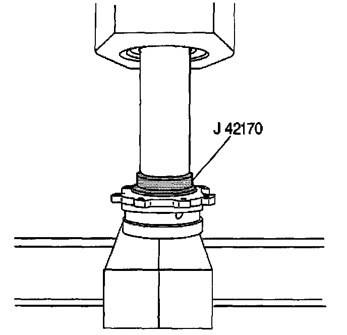
5. Install the drive pinion rear bearing inner race into the drive pinion housing using the J 42170 and a hydraulic press.
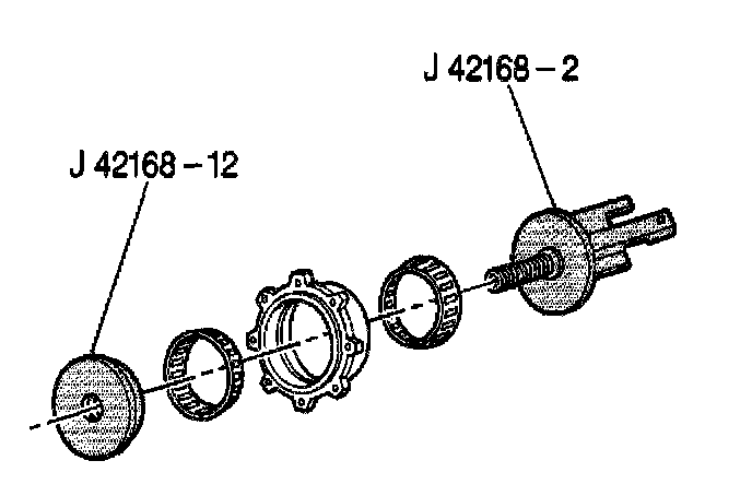
6. Assemble the pinion bearings, the J 42168-2 and the J 42168-12 to the pinion housing.
7. Tighten the tools until snug.
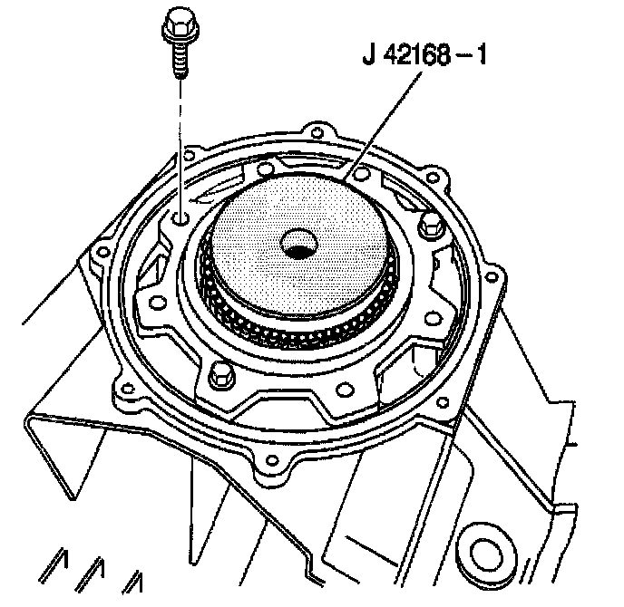
8. Install two M10 x 1.5 mm studs to the differential carrier.
During installation of the pinion housing, it is necessary to align the holes in the housing flange with the threaded holes in the differential housing.
Install the pinion housing (with tools and bearings) into the pinion bore of the differential housing.
If necessary, use a heat gun to heat the housing,
9. Remove the alignment studs.
10. Install a minimum of three pinion housing bolts.
^ Tighten the pinion housing bolts to 55 Nm (41 ft. lbs.).
NOTICE: Refer to Fastener Notice in Service Precautions.
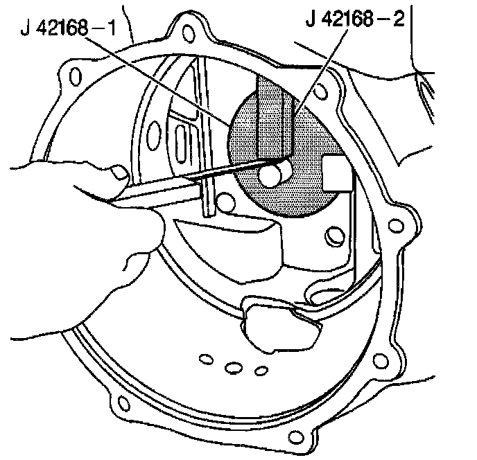
11. Using a feeler gauge and measure distance the between the tip of J 42168-1 and the J 42168-2.
IMPORTANT: If the pinion gear has a plus (+) or minus (-) number (metric value) stamped on the end, the shim thickness must be adjusted by that amount.
12. Subtract the measured value from 2.75 mm (0.10826 inch).
This is total A.
13. Add the number stamped on the pinion to total A.
This is total B.
IMPORTANT: Total B may increase or decrease based on the pinion number. The number stamped on the pinion may be either a plus or minus (-) value.
14. See the example below for proper computation of the shim thickness:
14.1 2.75 mm (0.10826 inch) is the predetermined value.
14.2 1.20 mm (0.0472 inch) is the feeler gauge example value.
14.3 1.55 mm (0.061 inch) is total A after subtraction.
14.4 -0.04 mm (-0.0016 inch) is the example value stamped on the pinion.
14.5 1.51 mm (0.059 inch) is shim total B. It may be necessary to round the shim total to obtain the proper shims, If the number is past the midpoint value, round the number to the next decimal value.
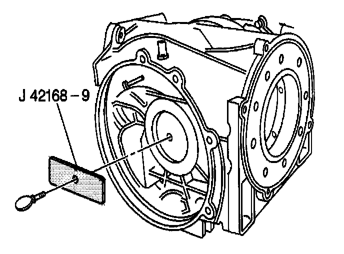
15. Remove the J 42168-9 and thumbscrew from the J 42168-9.
16. Remove the J 42168-9 from the differential carrier.