Rear Axle Assemble
^ Tools Required- J 42155 Differential Case Assembly Lifter
- J 25070 Heat Gun
- J 42164 Pinion Gear Holder
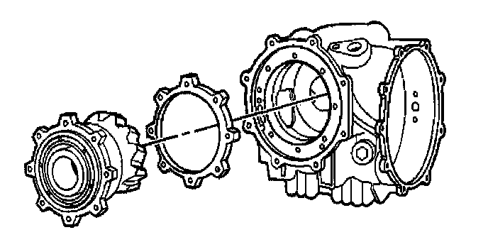
1. Install the drive pinion shim pack onto the pinion cartridge.
IMPORTANT: If the drive pinion cartridge has not been disassembled, reuse the original pinion cartridge shims that were removed during differential disassembly.
If the drive pinion cartridge has been disassembled, refer to Pinion Depth Adjustment for the proper shim sizes.
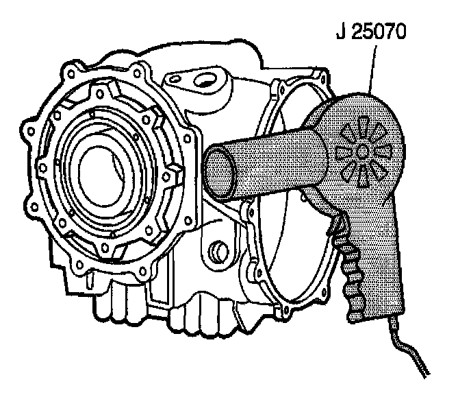
2. If necessary, heat the differential carrier around the drive pinion cartridge opening using the J 25070.
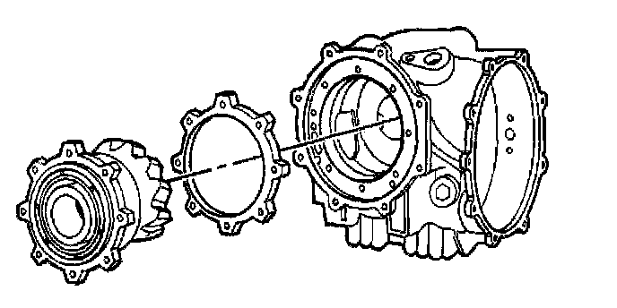
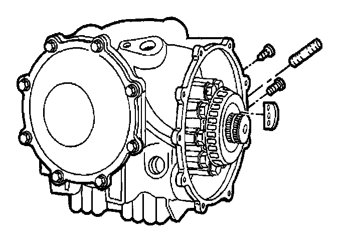
3. Install the drive pinion cartridge into the differential carrier.
The use of M10 x 1.5 mm studs will assist in properly aligning the pinion cartridge, shim pack, and housing.
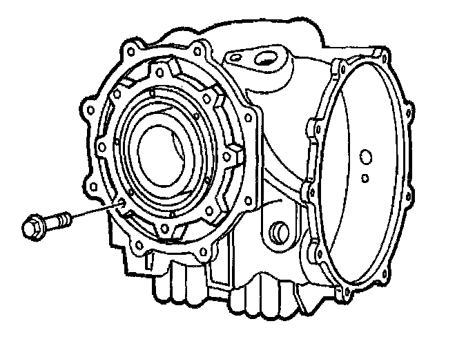
4. Install drive pinion cartridge bolts.
^ Tighten the drive pinion cartridge bolts to 55 Nm (41 ft. lbs.).
NOTICE: Refer to Fastener Notice in Service Precautions.
5. Check pinion rotating torque using the J 42164 and a torque wrench.
IMPORTANT: The pinion rotating torque should be no greater than 3 Nm (22 inch lbs.).
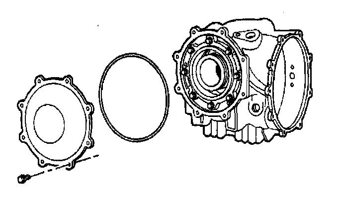
6. Install the rear differential carrier cover, O-ring, and rear cover bolts.
^ Tighten the rear cover bolts to 10 Nm (89 inch lbs.).
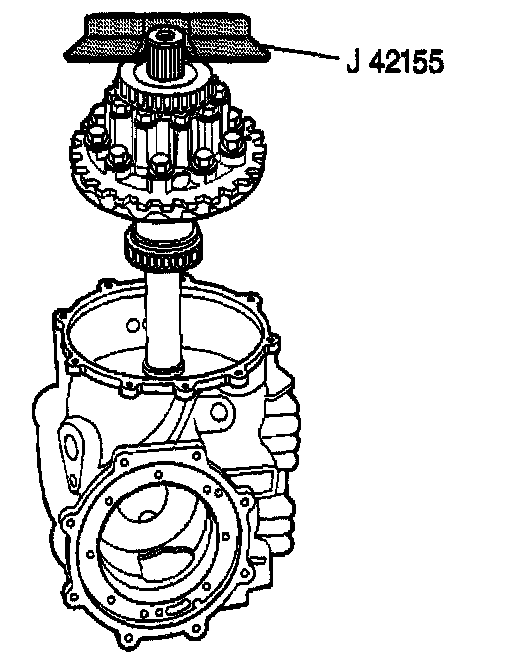
7. Install the differential case assembly in the differential carrier using the J 42155.
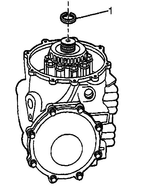
8. Install the C-clip (1) onto the right output shaft.
9. Apply threadlock GM P/N 1052942 or equivalent to the threads of the transmission stud mounting block retaining bolts.
10. Install the right side transmission stud mount and bolts.
^ Tighten the transmission stud mount bolts to 10 Nm (89 inch lbs.).
IMPORTANT: Note the installed position of the stud mounting block.
The mounting block, when installed properly, should be seated completely against the inside of the housing.
11. Apply threadlock GM P/N 1052942 or equivalent to the threads of the transmission stud. Apply threadlock only to the end of the stud that will install into the mounting block.
12. Install the right side transmission mounting stud to the differential carrier.
^ Tighten the right side transmission mounting stud to 40 Nm (30 ft. lbs.).
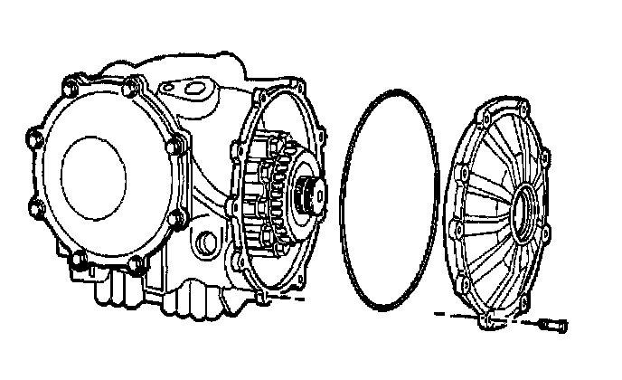
13. Install the right side differential carrier cover, O-ring, and the right side cover bolts.
^ Tighten the right side cover bolts to 25 Nm (18 ft. lbs.).
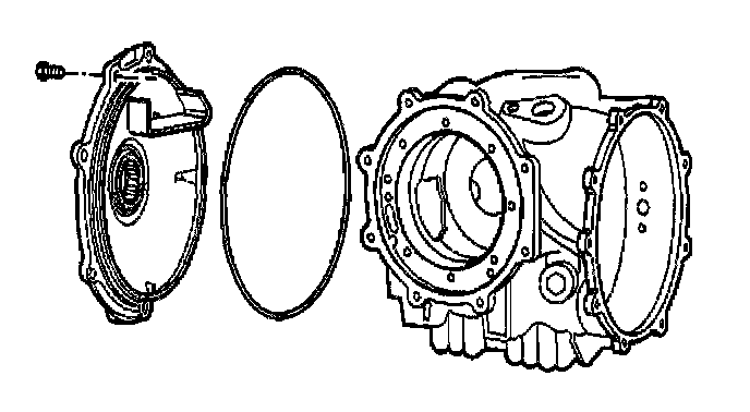
14. Install the magnet, left side differential carrier cover, O-ring seal, and bolts,
^ Tighten the cover bolts to 25 Nm (18 ft. lbs.).
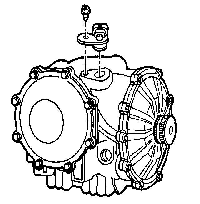
15. Install the vehicle speed sensor and bolt.
^ Tighten the vehicle speed sensor bolt to 10 Nm (89 inch lbs.).
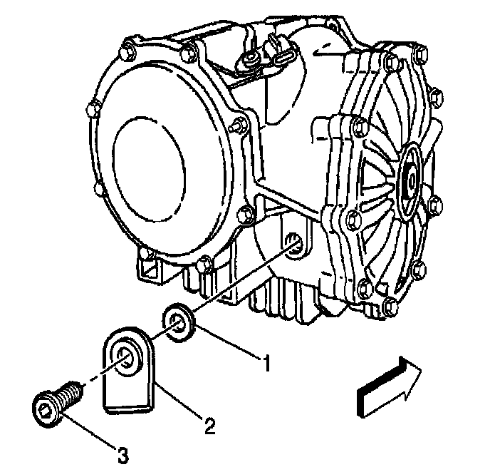
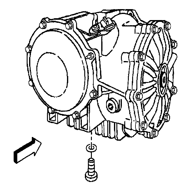
16. Install the axle lubricant fill plug (3), lubricant fill tag (2), and washer (1).
^ Tighten the axle lubricant fill plug (3) to 35 Nm (26 ft. lbs.).
17. Install the drain plug and washer.
^ Tighten the drain plug to 35 Nm (26 ft. lbs.).