Timing Cover: Service and Repair
Removal Procedure^ Tools Required
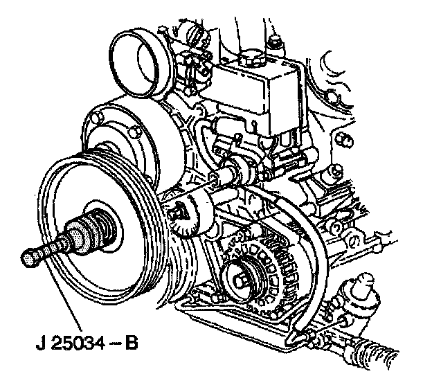
- J 25034-B Power Steering Pump Pulley Remover
Caution: Refer to Battery Disconnect Caution in Service Precautions.
1. Disconnect the negative battery cable.
2. Drain the engine oil.
3. Drain the engine coolant.
4. Disconnect the Intake Air Temperature (IAT) sensor electrical connector.
5. Remove the air intake duct.
6. Loosen the coolant pump pulley bolts.
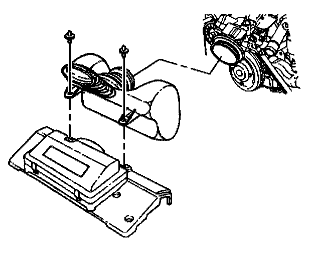
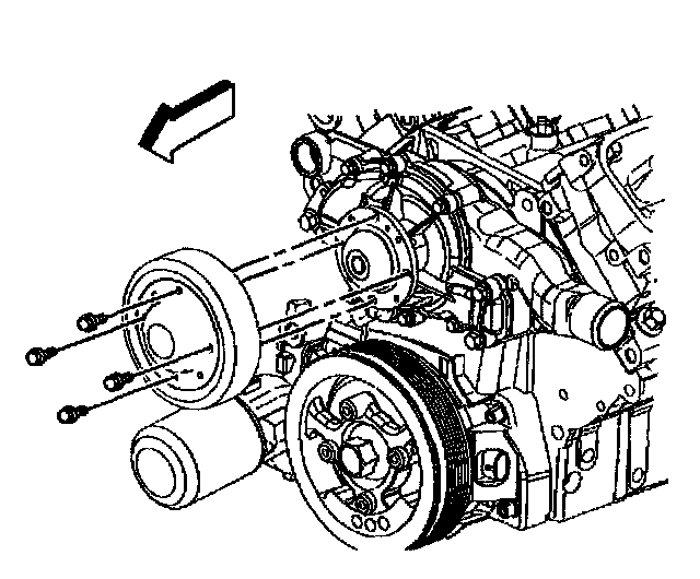
7. Remove the drive belt tensioner.
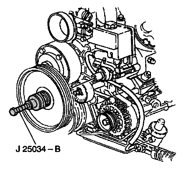
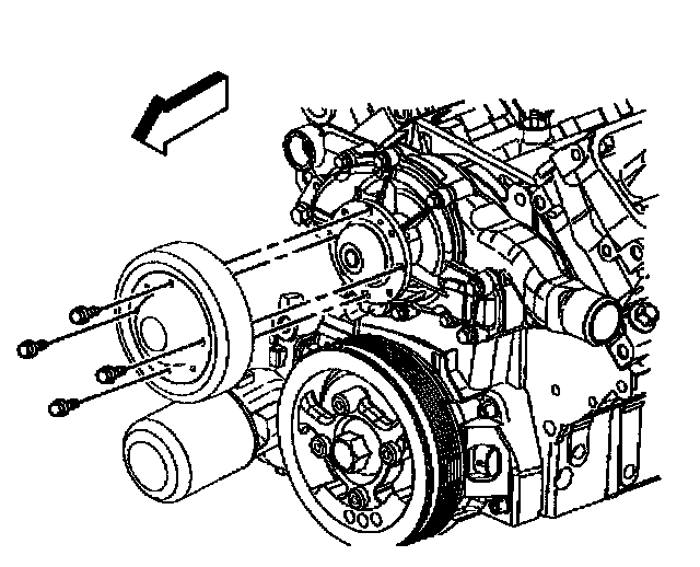
8. Use the J. 25034-B to remove the power steering pump pulley.
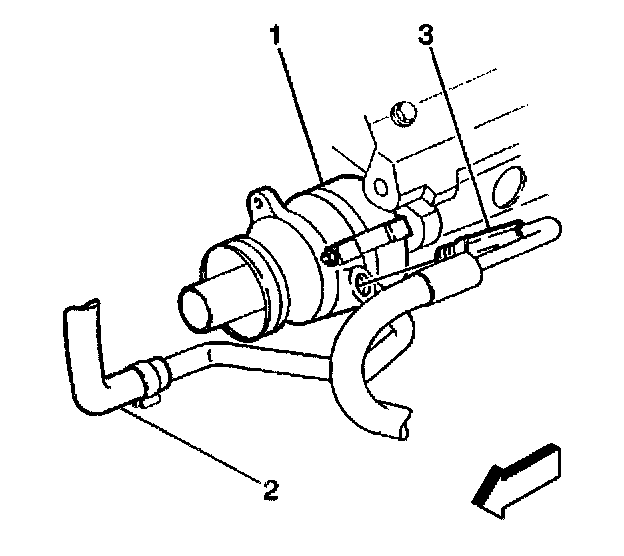
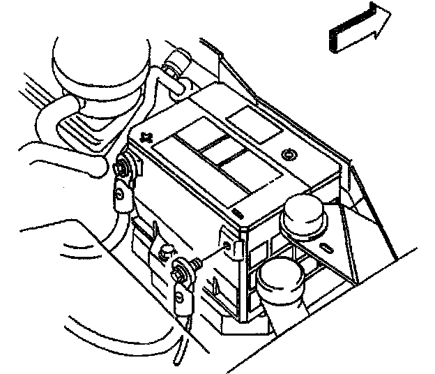
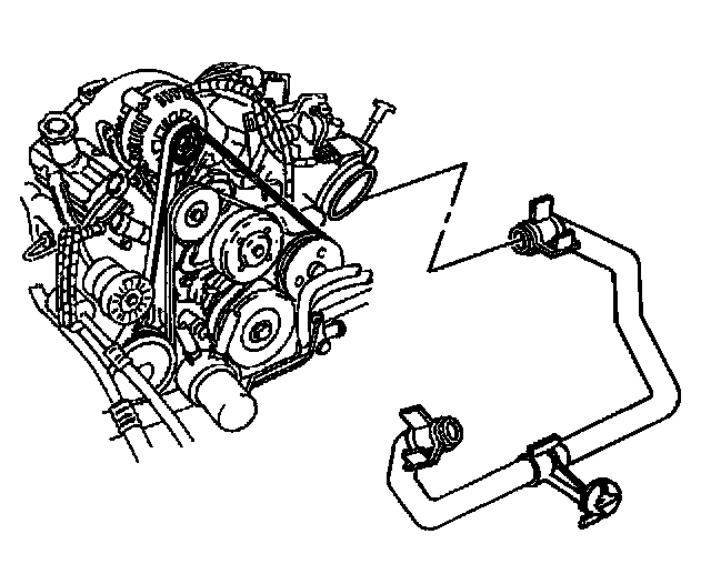
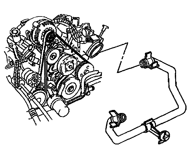
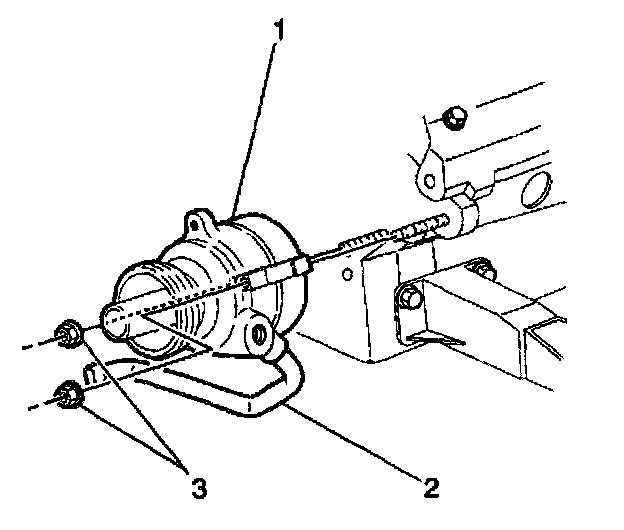
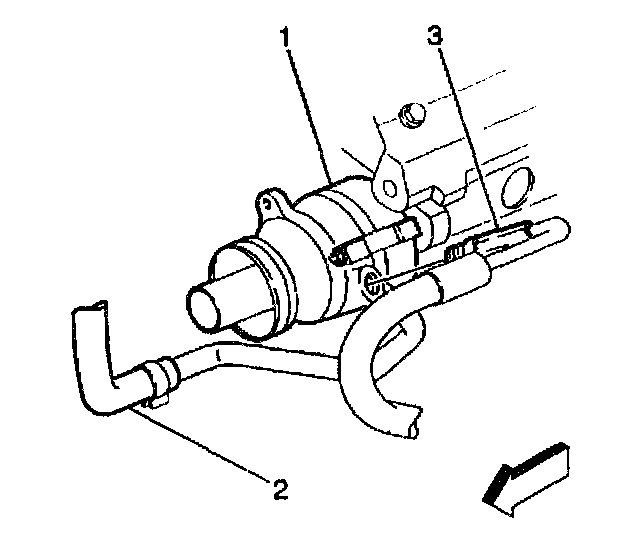
9. Place a drain pan under the power steering pump (1).
10. Disconnect the inlet hose (3) from the power steering pump (1).
11. Reposition the hose clamp on the return line (2).
12. Disconnect the reservoir hose return line (2) from the power steering pump (1).
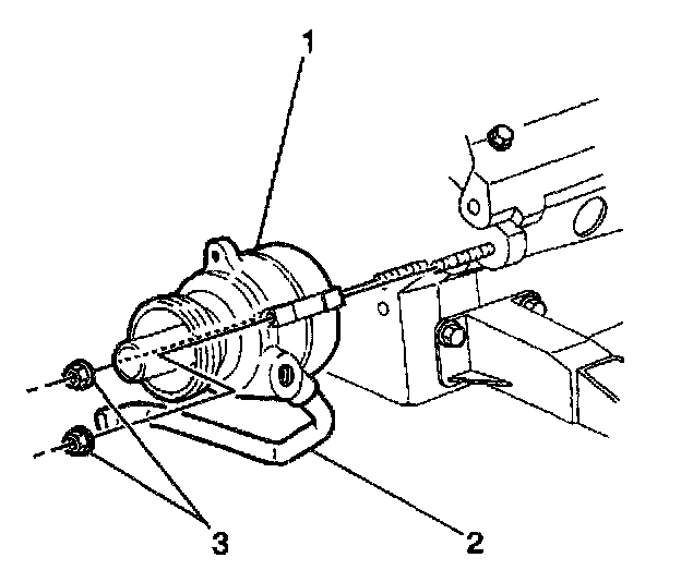
13. Remove the power steering pump nuts (3).
14. Remove the power steering pump (1).
15. Raise and suitably support the vehicle. Refer to Vehicle Lifting.
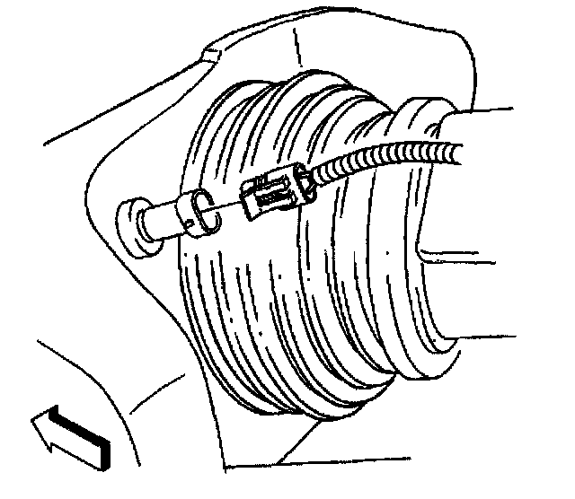
16. Remove the crankshaft balancer.
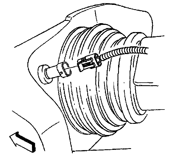
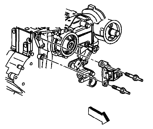
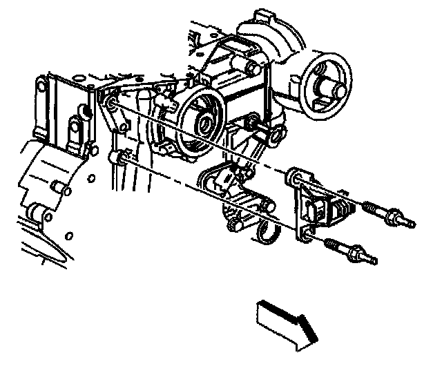
17. Disconnect the crankshaft position sensor electrical connector.
18. Remove the crankshaft position sensor shield.
19. Remove the crankshaft position sensor studs.
20. Remove the crankshaft position sensor.
21. Remove the oil pan to front cover bolts.
22. Loosen the oil pan bolts, to drop the oil pan slightly in order to add clearance for the front cover installation.
23. Lower the vehicle.
24. Remove the coolant pump pulley bolts.
25. Remove the coolant pump pulley.
26. Remove the radiator outlet hose from the front cover.
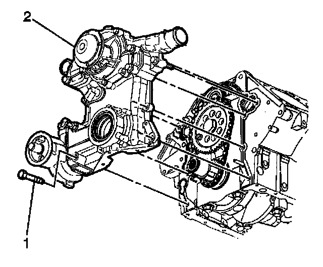
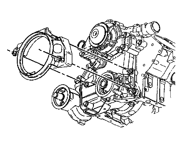
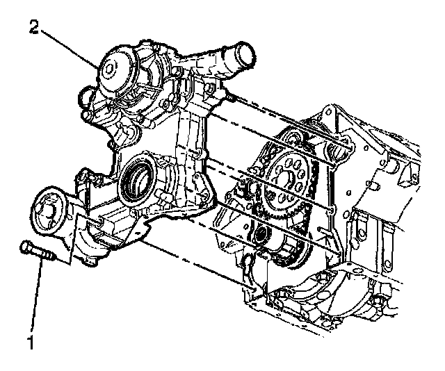
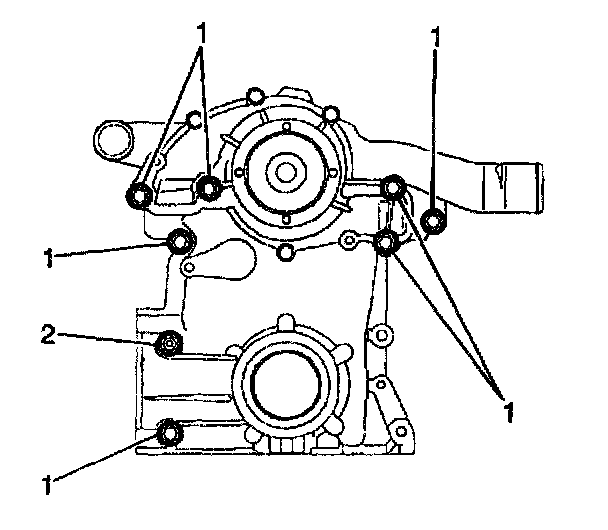
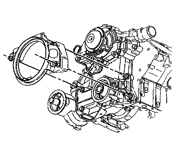
27. Remove the engine front cover studs and bolts (1).
28. Remove the engine front cover (2).
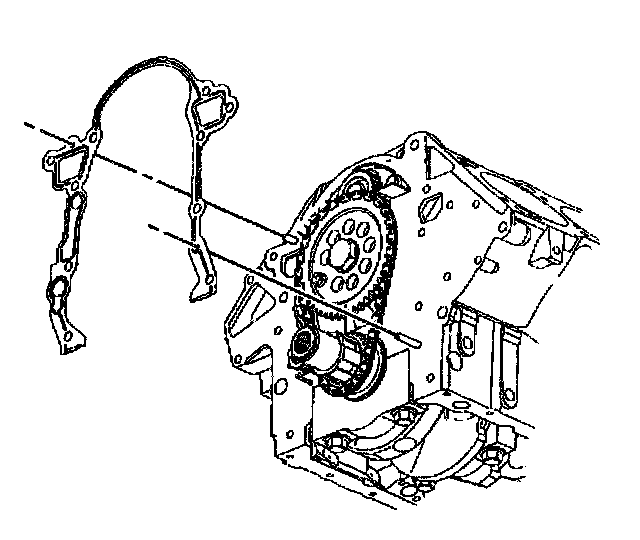
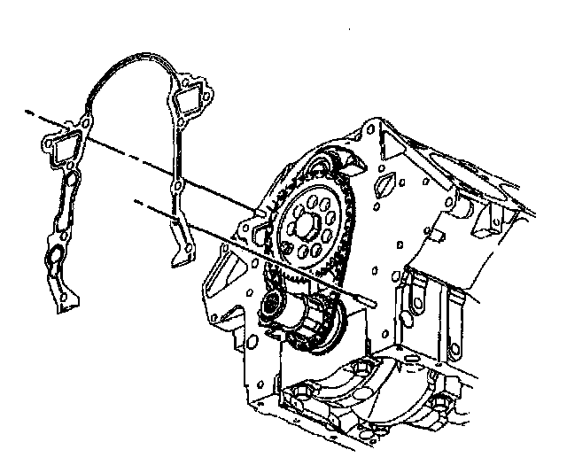
29. Remove the engine front cover gasket from the engine block.
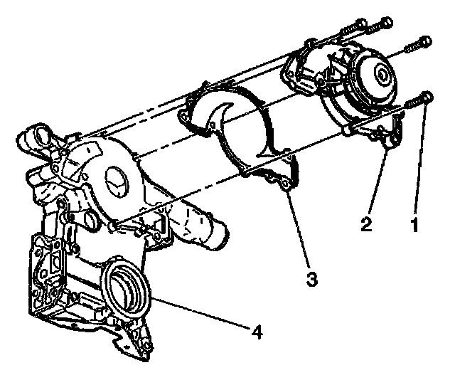
30. Remove the coolant pump bolts (1).
31. Remove the coolant pump (2).
32. Remove the coolant pump gasket (3) from the front cover (4).
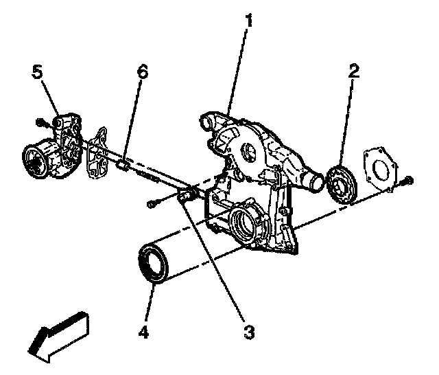
33. If replacing the front cover (1), disassemble the following components:
^ Oil pump gear set (2)
^ Camshaft sensor (3)
^ Oil filter adapter (5) and gasket
^ Oil pressure relief valve (6) and spring
34. Remove the crankshaft front oil seal (4).
35. Clean the engine front cover and engine block surfaces.
Installation Procedure
^ Tools Required
1. J 36660 Torque Angle Meter
2. J 35354 Seal Installer
3. J 25033-B Power Steering Pump Pulley Installer
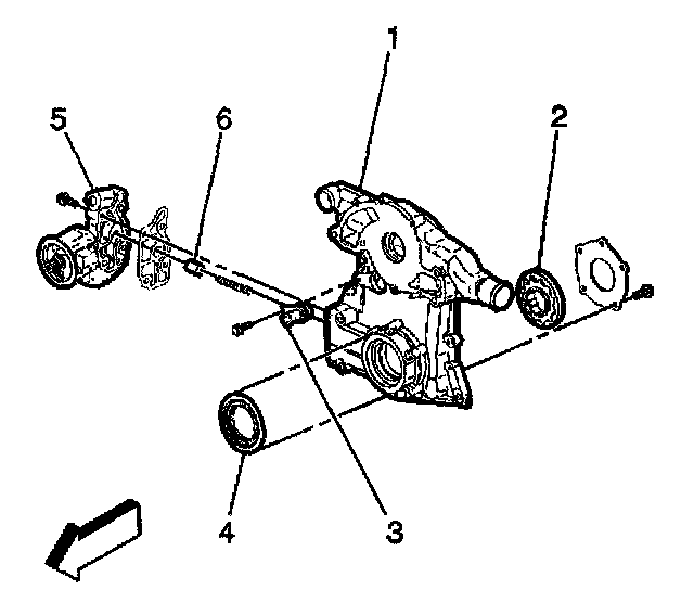
1. If replacing the front cover (1), assemble the following parts:
^ Oil pump gear set (2)
^ Camshaft sensor (3)
^ Oil filter adapter (5) and a new gasket
^ Oil pressure relief valve (6) and spring
2. Install a new crankshaft front oil seal (4)
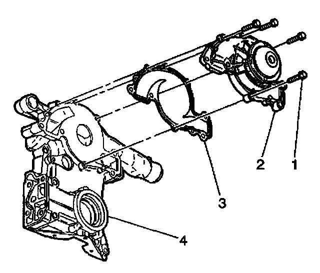
3. Install the coolant pump gasket (3) to the front cover (4).
4. Install the coolant pump (2).
Notice: Refer to Fastener Notice in Service Precautions.
5. Install the coolant pump bolts (1).
^ Tighten the coolant pump bolts (1) to 15 Nm (11 ft. lbs.). Use the J 36660 to torque the coolant pump bolts (1) an additional 80 degrees.
6. Install a new engine front cover gasket to the engine block.
7. Install the engine front cover (2).
8. Apply sealant GM P/N 12346004 or equivalent to the engine front cover bolts (1) and stud (2).
9. Install the engine front cover bolts (1) and stud (2).
^ Tighten the front cover bolts (1) and stud (2) to 20 Nm (15 ft. lbs.). Use the J 36660 to torque the front cover bolts (1) and stud (2) an additional 40 degrees.
10. Install the radiator outlet hose to the front cover.
11. Install the coolant pump pulley.
12. Install coolant pump pulley bolts.
^ Tighten the coolant pump pulley bolts to 13 Nm (115 inch lbs.).
13. Raise and suitably support the vehicle. Refer to Vehicle Lifting.
14. Install the oil pan to front cover bolts.
^ Tighten the oil pan bolts to 14 Nm (10 ft. lbs.).
15. Install the crankshaft position sensor.
16. Apply sealant GM P/N 12346004 or equivalent to the crankshaft position sensor studs.
17. Install the crankshaft position sensor studs.
^ Tighten the crankshaft position sensor studs to 20 Nm (15 ft. lbs.). Use the J 36660 to torque the crankshaft position sensor studs an additional 40 degrees.
18. Install the crankshaft position sensor shield.
19. Connect the crankshaft position sensor electrical connector.
20. Install the crankshaft balancer.
21. Lower the vehicle.
22. Install the power steering pump (1).
23. Install the power steering pump nuts (3).
^ Tighten the power steering pump nuts (3) to 30 Nm (23 ft. lbs.).
24. Connect the reservoir hose return line (2) to the power steering pump (1).
25. Position the hose clamp on the return line (2).
26. Connect the inlet hose (3) to the power steering pump (1).
^ Tighten the inlet hose (3) fitting to 28 Nm (21 ft. lbs.).
27. Use the J 25033-B to install the power steering pump pulley.
28. Remove the J 25033-B.
29. Install the drive belt tensioner.
30. Install the air intake duct.
31. Connect the Intake Air Temperature (IAT) sensor electrical connector.
32. Refill the engine oil.
33. Refill the engine coolant.
34. Connect the negative battery cable.