Transmission Replacement
Removal Procedure- Tools Required
- J 35944-A Oil Cooler and Line Flusher
- J 38778 Door Trim Pad and Garnish Clip Remover
- J 37096 Flywheel Holder
Caution: Refer to Battery Disconnect Caution in Service Precautions.
1. Disconnect the battery negative cable. Refer to Battery Negative Cable Disconnect/Connect Procedure in Starting and Charging
2. Remove the throttle body air inlet duct. Refer to Powertrain Management.
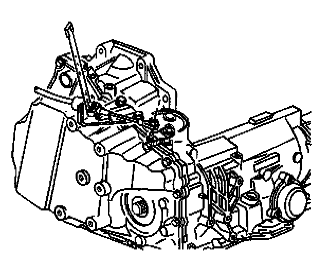
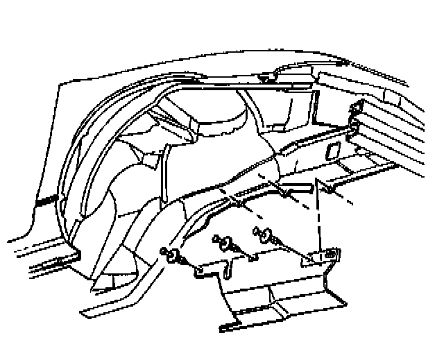
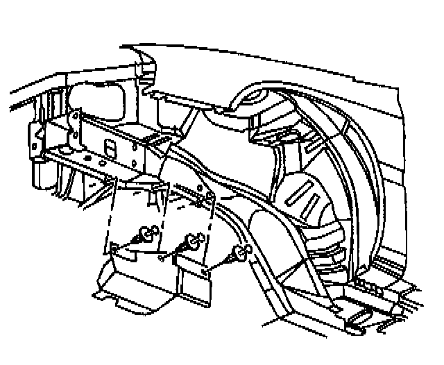
3. Disconnect the electrical connectors from the transaxle.
4. Remove the transaxle range selector cable retainer from the cable.
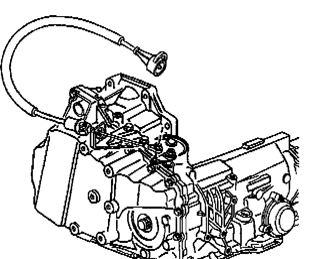
5. Disconnect the transaxle range selector cable from the transaxle.
6. Remove the transaxle wiring grounds from the transaxle.
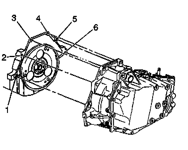
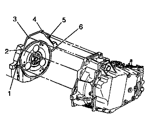
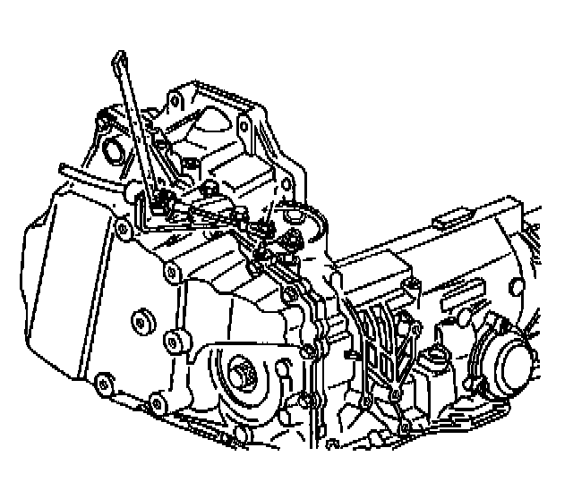
7. Remove the upper transaxle bolts (3,4,5) and the stud (2).
8. Install the engine support fixture.
9. Raise and support the vehicle. Refer to Vehicle Lifting.
10. Remove the front wheels. Refer to Tire and Wheel Removal and Installation in Wheels, Tires and Alignment
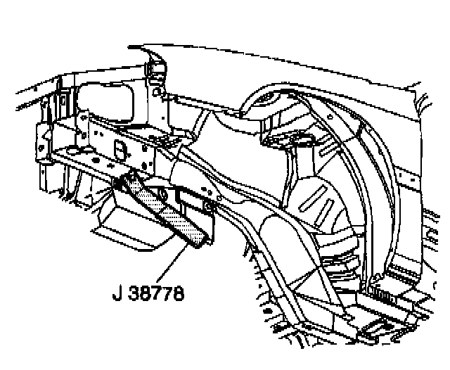
11. Use the J 38778 in order to remove the push-in retainers from the left engine splash shield.
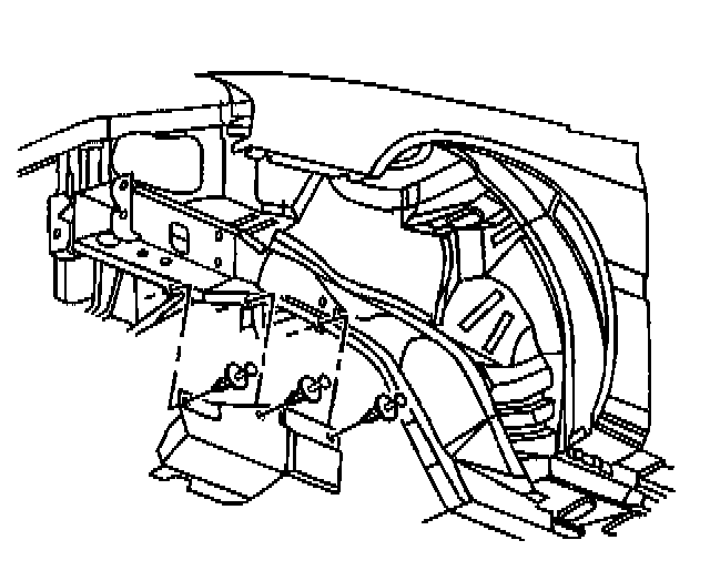
12. Remove the left engine splash shield from the vehicle.
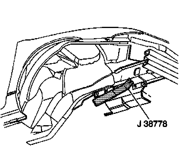
13. Use the J 38778 in order to remove the push-in retainers from the right engine splash shield.
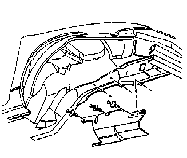
14. Remove the right engine splash shield from the vehicle.
15. Remove the frame from the vehicle. Subframe
16. Remove the starter motor.
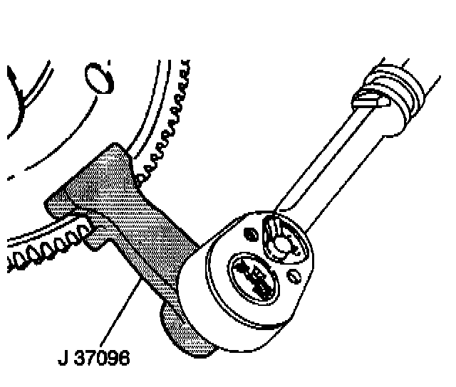
17. Use J 37096 in order to gain access to the torque converter bolts and prevent the flywheel from turning.
18. Remove the torque converter bolts.
19. Disconnect the transaxle oil cooler pipes from the transaxle.
Important: Position and secure the wheel drive shafts out of the way.
20. Remove the wheel drive shafts from the transaxle.
21. Disconnect the vehicle speed sensor electrical connector. Refer to Vehicle Speed Sensor Replacement
Important: Ensure the transmission jack is properly secured to the transaxle.
22. Position a transmission jack under the transaxle and secure the transmission jack to the transaxle.
23. Remove the transaxle brace.
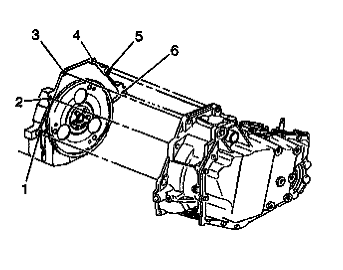
24. Remove the lower transaxle bolt (6) and stud (1).
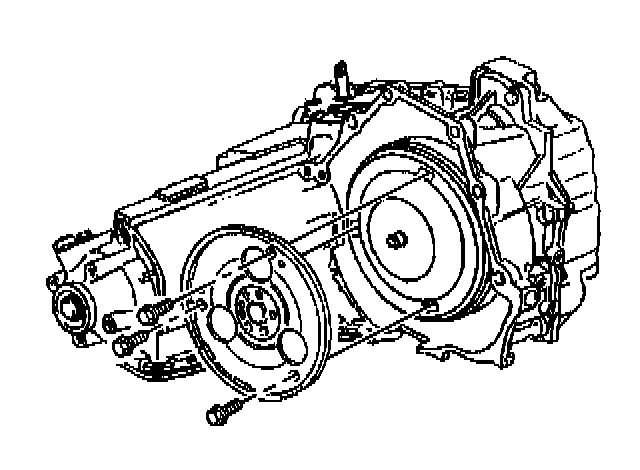
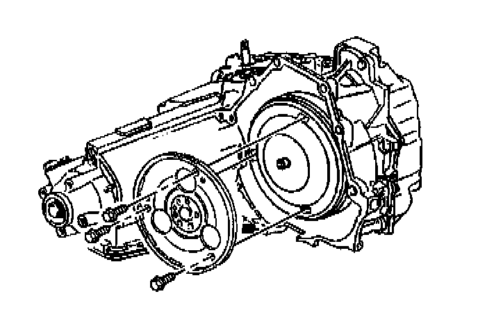
25. Remove the transmission from the vehicle.
Important: Use J 35944-A or equivalent to flush the following components whenever the transaxle is removed for overhaul or whenever the torque converter pump or the case is replaced:
26. Flush the transaxle oil cooler pipes and the transaxle oil cooler. Refer to Automatic Transmission Oil Cooler Flushing.
27. Transfer all necessary parts as needed.
Installation Procedure
Important: Ensure the transaxle is secured properly to the transmission jack.
1. Position the transaxle onto a transmission jack and secure the transaxle to the transmission jack.
2. Install the transaxle into the vehicle.
Notice: Refer to Fastener Notice in Service Precautions.
3. Install the lower transaxle bolt (6) and the stud (1).
- Tighten the lower transaxle bolts and the stud to 75 Nm (55 ft. lbs.).
4. Install the transaxle brace. Refer to Automatic Transmission Brace Replacement.
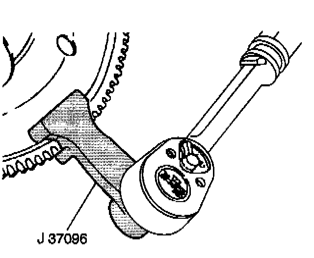
5. Use J 37096 in order to gain access to install the torque converter bolts and prevent the flywheel from turning.
6. Install the torque converter bolts.
- Tighten the torque converter bolts to 63 Nm (46 ft. lbs.).
7. Install the wheel drive shafts into the transaxle.
8. Install the transaxle oil cooler pipes to the transaxle. Refer to Automatic Transmission Oil Cooler Pipes Replacement.
9. Install the starter motor.
10. Install the frame to the vehicle. Refer to Frame Removal in Body and Frame.
11. Connect the vehicle speed sensor electrical connector. Refer to Vehicle Speed Sensor Replacement
12. Install the right engine splash shield.
13. Install the left engine splash shield.
14. Install the front wheels. Refer to Tire and Wheel Removal and Installation in Wheels, Tires and Alignment.
15. Lower the vehicle.
16. Remove the engine support fixture.
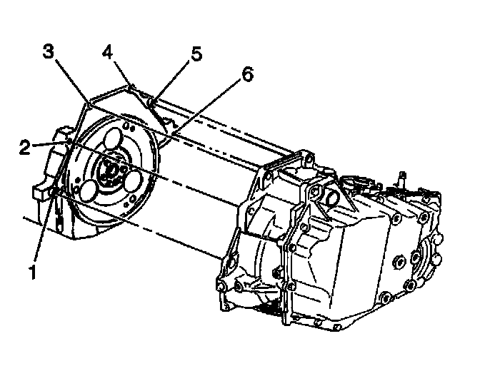
17. Install the upper transaxle bolts (3,4,5) and the stud (2).
- Tighten the upper transaxle bolts and the stud to 75 Nm (55 ft. lbs.).
18. Install the transaxle wiring grounds to the transaxle.
19. Install the electrical connectors to the transaxle.
20. Install the transaxle range selector cable to the transaxle range selector cable bracket.
21. Install the automatic transaxle range selector cable retainer to the cable
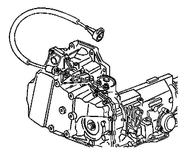
22. Connect the transaxle range selector cable to the range selector manual lever.
23. Install the throttle body air inlet duct. Refer to Air Cleaner Assembly Replacement in Powertrain Management.
24. Connect the battery negative cable. Refer to Battery Negative Cable Disconnect/Connect Procedure in Starting and Charging.
Notice: Do NOT overfill the transaxle. The overfilling of the transaxle causes foaming, loss of fluid, shift complaints, and possible damage to the transaxle.
25. Fill the transaxle with automatic transmission fluid. Refer to Transmission Fluid Checking Procedure.
26. Inspect for automatic transmission fluid leaks. Refer to Fluid Leak Diagnosis.
27. Inspect for proper completion of the repairs. Refer to Road Test Procedure.
28. Perform a front end alignment.