Diagnostic System Check
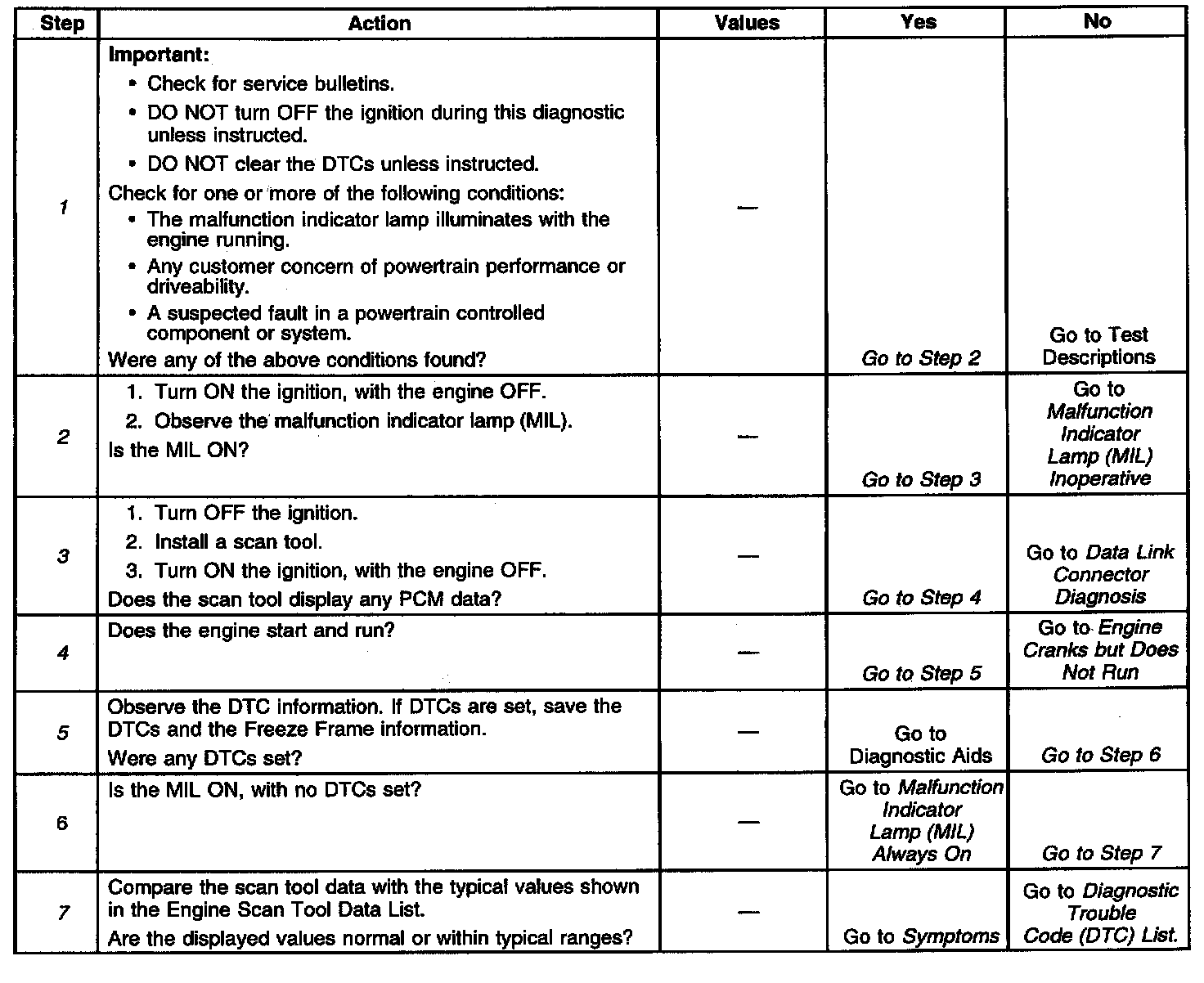
Diagnostic Chart:
Engine Controls Schematics: MIL And DLC:

Engine Controls Schematics: Power And Ground:

DESCRIPTION
The Powertrain OBD System Check is an organized approach to identifying a problem created by an electronic engine control system malfunction. The Powertrain OBD System Check is the starting point for any driveability concern diagnosis, because it directs the service technician to the next logical step in diagnosing the concern. Understanding the table and using it correctly will reduce diagnostic time and prevent the replacement of good parts.
DO NOT perform this check if a driveability concern is not present.
DIAGNOSTIC AIDS
^ Inspect all the related wiring and connections for an intermittent malfunction, including the connections at the PCM. Inspect the electrical terminals for the following conditions:
- Any damage
- Any corrosion
- Proper seating
^ Before proceeding to the applicable DTC table consider all of the items below:
- Check for related service bulletins.
- If multiple DTCs are stored, refer to the DTC tables using the following priority:
^ Any PCM error DTCs
^ Any system voltage DTCs
^ Any component level DTCs (sensors, switches, relays, output drivers, etc.)
^ Any system level DTCs (misfire, fuel trim, HO2S lean or rich, etc.
- First failures of Type B DTCs will store in Last Test Failed, but not in History. When the MIL is on and a DTC is displayed in History, a current fault is indicated.
- Transmission DTCs are not located. Refer to Automatic Transmission Diagnostic Information and Procedures.
- If the scan tool is unable to record DTC information, then record the DTC information on paper.
^ For intermittents, refer to Symptoms.
TEST DESCRIPTION
The numbers below refer to the step numbers in the diagnostic table.
1. The OBD System Check should not be performed unless one of the concerns noted is present, failure to follow this procedure could lead to misdiagnosis of the system.
2. The MIL should be ON steady with the ignition ON and engine OFF.
3. Checking if the PCM and the scan tool can communicate.
4. This step checks if the vehicle starts.
5. Observes the DTC information. Ensures that items listed in Diagnostic Aids are considered before proceeding to the applicable DTC table.
7. Before proceeding to Symptoms or Components, check for related service bulletins. The diagnostic tables are designed for use with a properly functioning scan tool. If a faulty scan tool is suspected connect it to another vehicle to verify operation. Serial data communications must be corrected before beginning any other diagnostic procedure. OBD II serial data may not transmit if system voltage is less than 9.0 volts or more than 16.0 volts. DO NOT clear DTCs unless directed by a diagnostic procedure. Clearing DTCs will also clear valuable Freeze Frame data.