Disassembly Procedure
TOOLS REQUIRED^ J 39200 Digital Multimeter
^ J 28509-A Bearing Remover
^ J 26900-5 Vernier Caliper
^ J 38276 Puller Adapter
^ J 35452 Generator Pulley Remover/Installer
^ J 35419 Bearing Installer
^ J 22888 Universal Puller
^ J 29533-A/BT-8127 Oxygen Sensor Wrench
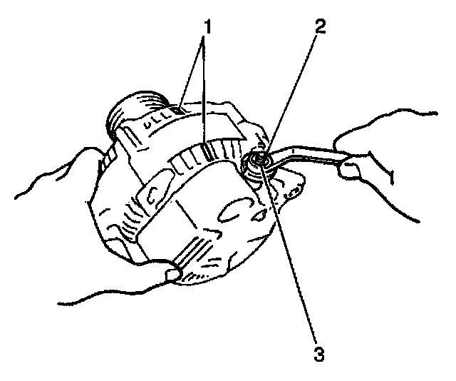
1. Remove the generator from the vehicle.
2. Refer to Charging System Description.
3. Scribe matchmarks (1) on the front and rear housings to ensure proper assembly.
4. Remove the nut (3) and the terminal insulator (2).
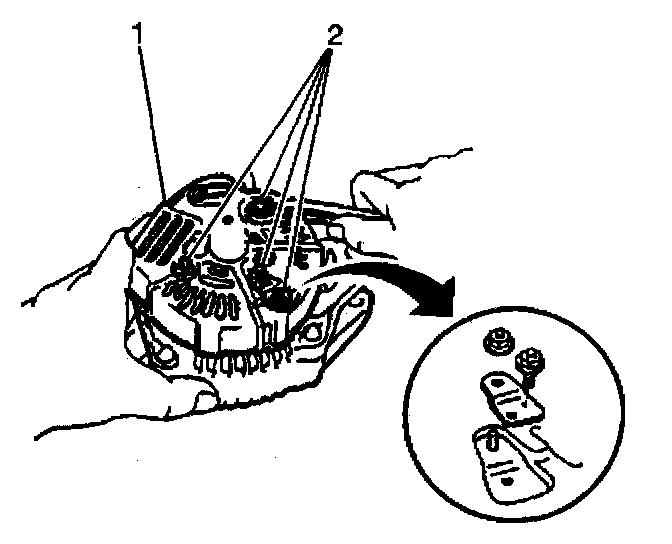
5. Remove the following from the end cover (1):
^ 1 bolt
^ 3 nuts (2)
^ The plate terminal
6. Remove the end cover.
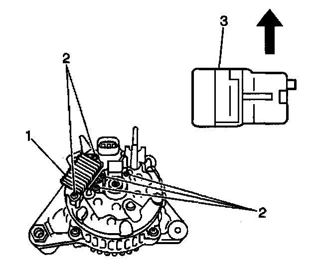
7. Remove the brush holder cover.
8. Remove the 5 screws (2).
IMPORTANT: Note the correct orientation of the brush holder for easier installation.
9. Remove the brush holder (3).
10. Remove the voltage regulator (1).
11. Remove the seal.
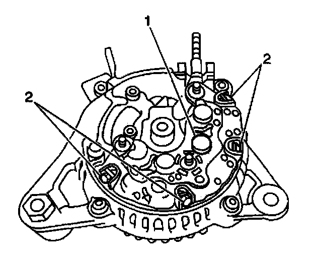
12. Remove the 4 screws (2) and the rectifier holder (1).
13. Remove the 4 rubber insulators.
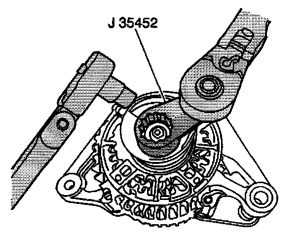
14. Remove the pulley nut using the J 35452 or the J 39194-B and a 10 mm socket. Loosen the nut with the 7/8 in box end wrench while holding the rotor shaft with the 10 mm socket wrench.
15. Remove the pulley.
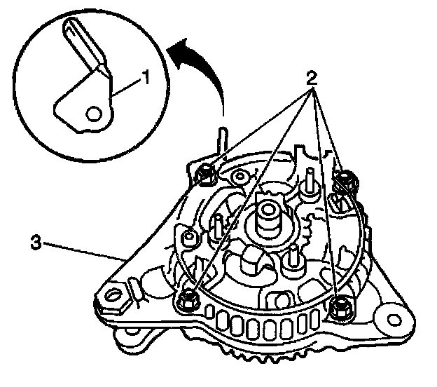
16. Remove the 4 nuts (2) and the clip (1) from the rectifier end frame.
17. Remove the rectifier end frame using the J 28509-A.
18. Remove the washer from the rotor.
19. Remove the rotor from the drive end frame.
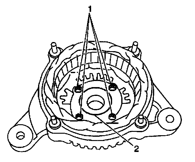
20. Inspect the front bearing (2) for rough operation, wear or damage. If necessary, replace the front bearing.
21. Remove the 4 screws (1).
22. Remove the bearing retainer.
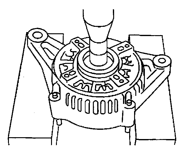
23. Press out the front bearing using an appropriate adaptor.
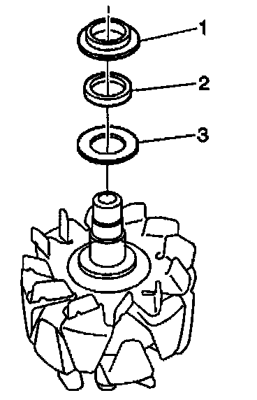
24. Inspect the rear bearing (2) for rough operation, wear or damage. If necessary, replace the rear bearing.
25. Remove the rear bearing outer cover (1).
IMPORTANT: Do not damage the rotor fan during bearing removal.
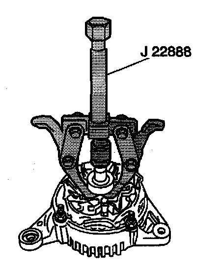
26. Remove the rear bearing from the rotor using the J 22888.
27. Remove the rear bearing inner cover.