Measuring Procedure
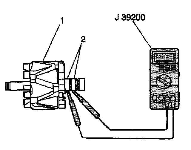
1. Measure the resistance between the rotor slip rings (2) with the J 39200. If the resistance is greater than specifications, replace the rotor.
Rotor Slip Ring Resistance
2.7-3.1 ohms at 20°C (68°F)
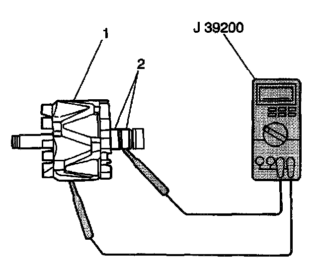
2. Measure the resistance between the rotor slip rings (2) and the rotor (1) with the J 39200. If the resistance is less than 5 ohms, replace the rotor.
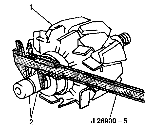
3. Measure the rotor slip rings (2) with the J 26900-5. If the diameter is less than the minimum, or if the slip rings are rough or scored, replace the rotor.
Standard Slip Ring Diameter
14.2-14.4 mm (0.559-0.567 in)
Minimum Slip Ring Diameter
12.8 mm (0.504 in)
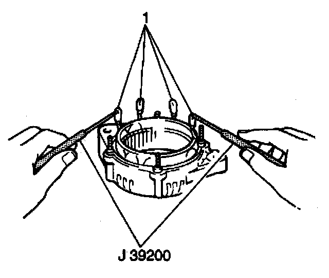
4. Measure the resistance between all stator leads (1) with the J 39200. If the resistance is greater than 5 ohms for any measurement, replace the stator.
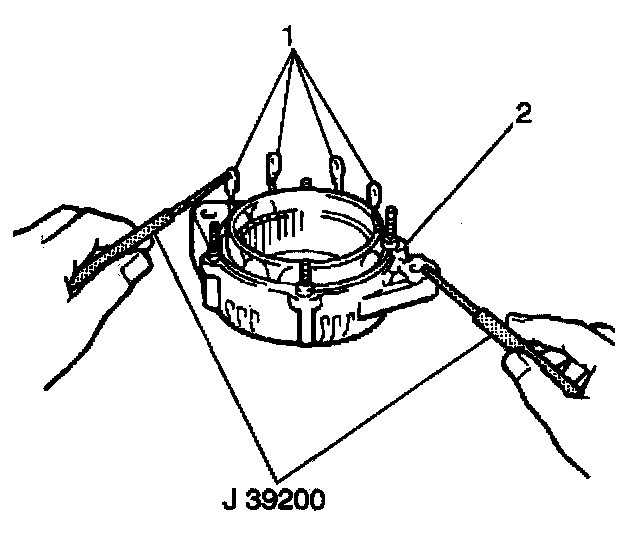
5. Measure the resistance between all stator leads (1) and the stator core with the J 39200. If the resistance is less than 5 ohms, replace the stator.
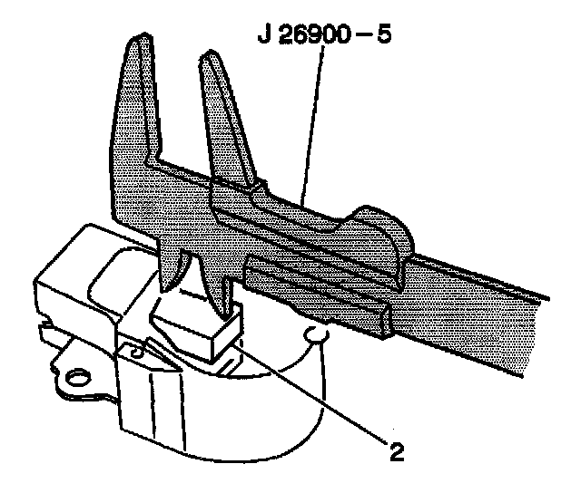
6. Measure the exposed brush length (2) with the J 26900-5. If the exposed length is less than the minimum, replace the brush holder assembly
Standard Exposed Brush Length
10.5 mm (0.413 in)
Minimum Exposed Brush Length
1.5 mm (0.059 in)
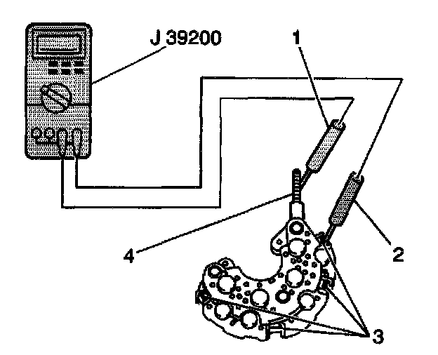
7. Measure the resistance between the rectifier positive terminal (4) and each rectifier terminal (3) with the J 39200. Reverse the probes and measure the resistance again. If the resistance is not less than 5 ohms in one measurement and greater than 5 ohms in the other measurement, replace the rectifier.
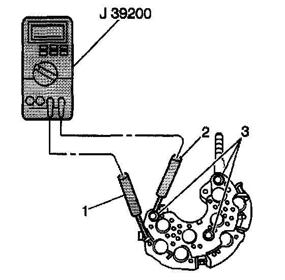
8. Measure the resistance between the rectifier negative terminal (3) and each rectifier terminal with the J 39200. Reverse the probes and measure the resistance again. If the resistance is not less than 5 ohms in one measurement and greater than 5 ohms in the other measurement, replace the rectifier.