Front Suspension Crossmember Replacement
- Tools Required- J 28467-B Universal Engine Support Fixture
- J 41803 Engine Support Fixture
- J 33432-A Transverse Spring Compressor
Removal Procedure
1. Remove the generator from the accessory mounting bracket. Refer to Generator Replacement in Starting and Charging.
2. Remove the washer pump/reservoir. Refer to Washer Pump/Reservoir Replacement in Wipers and Washer Systems.
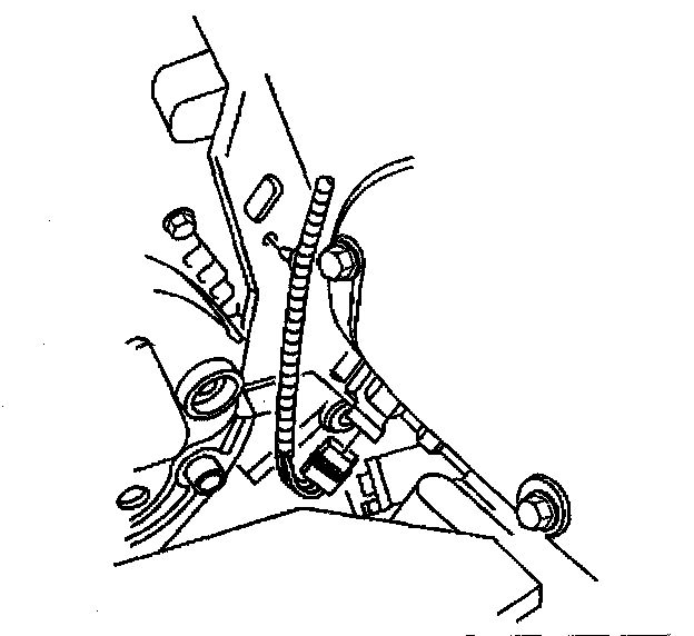
3. Remove the engine coolant temperature switch electrical connector and reposition.
4. Remove the front headlamp electrical connector and reposition.
5. Install J 41803 and J 28467-B and support the engine.
6. Raise and support the vehicle. Refer to Vehicle Lifting.
7. Remove the tire and wheel assemblies. Refer to Tire and Wheel Removal and Installation.
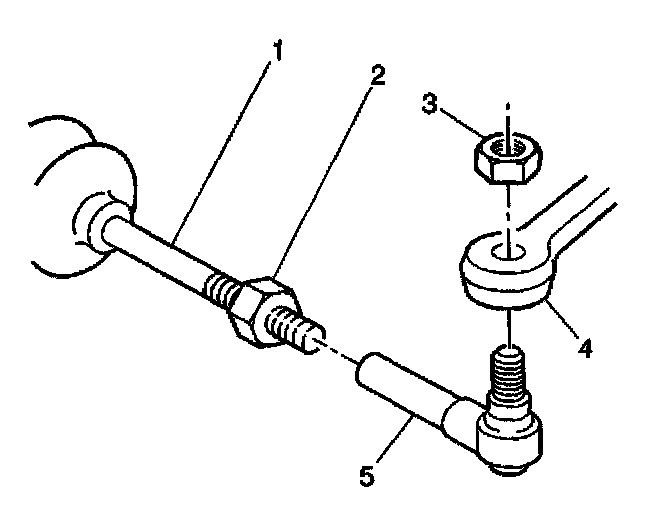
8. Remove the steering linkage outer tie rod end stud nuts (3). Refer to Tie Rod End Replacement - Outer in Power Steering.

9. Disconnect the shock absorber solenoid electrical connector, if equipped.
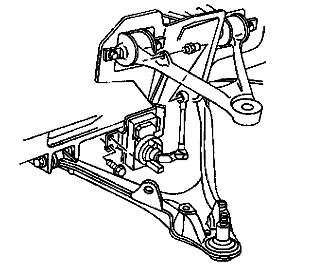
10. Disconnect the Real Time Damping (RTD) sensor links.
11. Remove the stabilizer shaft from the vehicle. Refer to Stabilizer Shaft Replacement.
12. Disconnect the intermediate shaft lower coupling from the steering gear. Refer to Intermediate Steering Shaft Replacement in Steering Wheel and Column-Tilt.
13. Remove the bolts from the Electronic Brake Control Module/Brake Pressure Modulator Valve (EBCM/BPMV) bracket. Refer to Brake Pressure Modulator Valve (BPMV) Bracket Replacement in Brakes and Traction Control.
14. Support and reposition the EBCM/BPMV and bracket away from the crossmember.

15. Remove the power steering gear mounting bolts.
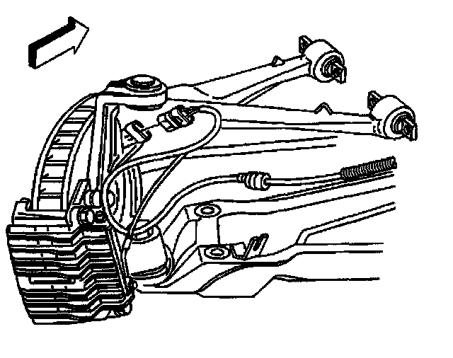
16. Remove the power steering fluid cooler from the crossmember.
17. Lift the power steering gear off of the crossmember and support.

18. Using the of 33432-A, remove the transverse spring from the vehicle. Refer to Front Transverse Spring Replacement.

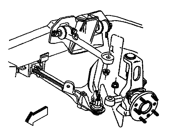
19. Disconnect the lower shock absorber bolts from the lower control arms.
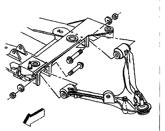
20. Remove the lower control arm bolts from the crossmember.
21. Place a transmission jack under the crossmember.
22. Remove the engine mount lower nuts. Refer to the following procedures:
- Engine Mount Replacement - Left in Engine.
- Engine Mount Replacement - Right in Engine.

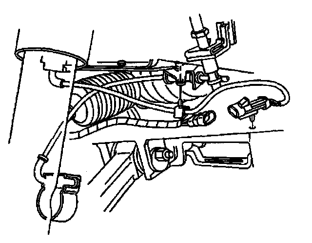
23. Disconnect the wheel speed sensor wiring harness from the crossmember.

24. Disconnect the electrical harness from the clips on the crossmember.
25. Disconnect the brake pipe from the clips on the crossmember.

26. Remove the crossmember mounting nuts.
27. Lower the crossmember out of the vehicle by removing the transmission jack from under the crossmember.
Installation Procedure
1. Raise the crossmember to the vehicle.
1.1. Align the crossmember dowel pins to the frame rails.
1.2. Align the engine mount studs.
Notice: Refer to Fastener Notice in Service Precautions.
2. Install new crossmember mounting nuts.
- Tighten the new crossmember mounting nuts to 110 Nm (81 ft. lbs.).
3. Install the engine mount lower nuts. Refer to one of the following procedures:
- Engine Mount Replacement - Left in Engine
- Engine Mount Replacement - Right in Engine
4. Fasten the wheel speed sensor wiring harness retaining clips to the crossmember.
5. Fasten the brake pipe to the retaining clips on the crossmember.
6. Connect the electrical harness to the clips on the crossmember.
7. Connect the brake pipe to the clips on the crossmember.
8. Install the transverse spring with the J 33432-A connected, to the crossmember. Refer to Front Transverse Spring Replacement.
9. Install the lower control arm to the crossmember. Refer to Lower Control Arm Replacement

10. Install the shock absorbers to the lower control alms.
- Tighten the shock absorber lower mounting nuts to 28 Nm (21 ft. lbs.).
11. Install the power steering gear to the crossmember.
- Tighten the power steering gear mounting bolts to 100 Nm (74 ft. lbs.).
12. Install the bolts to the brake pressure modulator valve bracket. Refer to Brake Pressure Modulator Valve (BPMV) Bracket Replacement in Brakes and Traction Control.
13. Connect the intermediate shaft to the steering gear. Refer to Intermediate Steering Shaft Replacement in Steering Wheel and Column-Tilt.
14. Install the steering linkage outer tie,rod ends to the steering knuckles. Refer to Tie Rod End Replacement - Outer in Power Steering.
15. Connect the RTD sensor links to the upper control arm, if equipped.
16. Connect the shock absorber solenoid electrical connector, if equipped.
17. Install the stabilizer shaft to the vehicles. Refer to Stabilizer Shaft Replacement.
18. Install the tire and wheel assemblies. Prefer to Tire and Wheel Removal and Installation.
19. Lower the vehicle.
20. Remove J41803and J28467-B from the engine.
21. Install the generator. Refer to Generator Replacement in Starting and Charging.
22. Install the washer pump/reservoir. Refer to Washer Pump/Reservoir Replacement in Wipers and Washer Systems.
23. Install the engine coolant temperature switch electrical connector.
24. Install the front headlamp electrical connector.
25. Connect the negative battery cable.
- Tighten the negative battery cable to 15 Nm (11 ft. lbs.).
26. Perform a vehicle front end alignment. Refer to Measuring Wheel Alignment.