Instrument Panel Electrical Center or Junction Block Replacement
REMOVAL PROCEDURE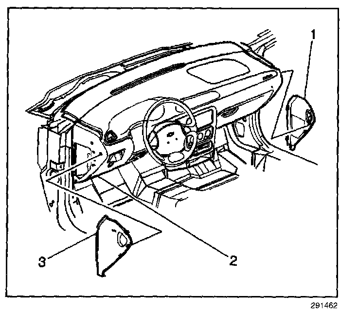
1. Disconnect the negative battery cable.
2. Remove the outer trim covers (1, 3) from the Instrument Panel (IP) carrier (2).
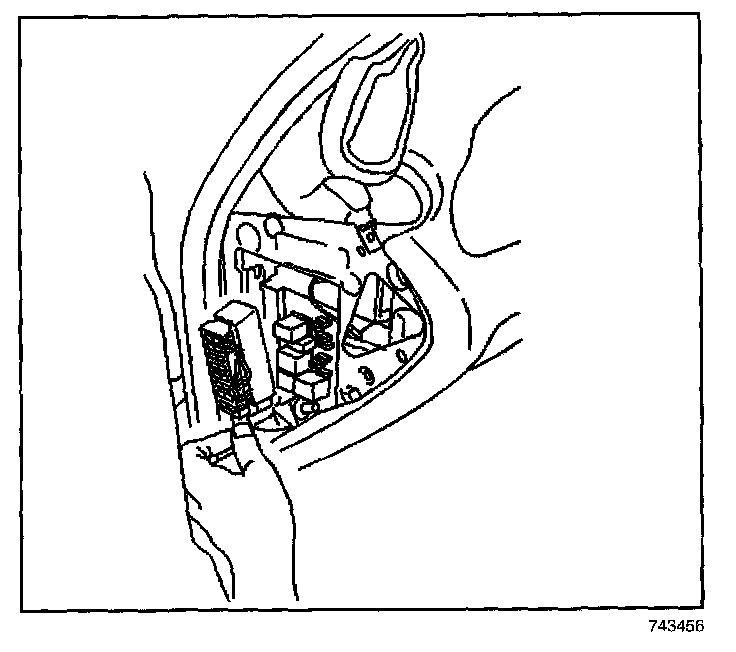
3. Loosen the outboard junction block electrical connector bolt. Disengage the outboard junction block electrical connector tabs from IP fuse block. Left side shown, right side similar.
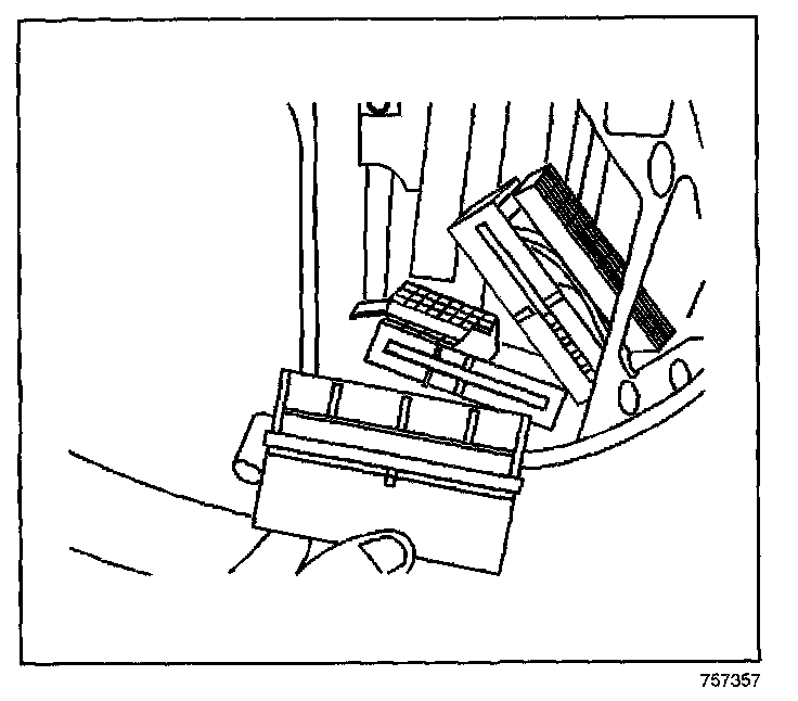
4. For the driver side only:
4.1. Remove the left half of the sound insulator from the IP carrier and disengage the wire harness from the cross vehicle beam.
4.2. Disengage the IP fuse block tabs from the cross vehicle beam.
4.3. Pull the IP fuse block away from the IP carrier.
4.4. Loosen the inboard junction block electrical connector bolts. Disengage the junction block electrical connector tabs from the IP fuse block.
4.5. Note where the fuses and relays are located and remove if required.
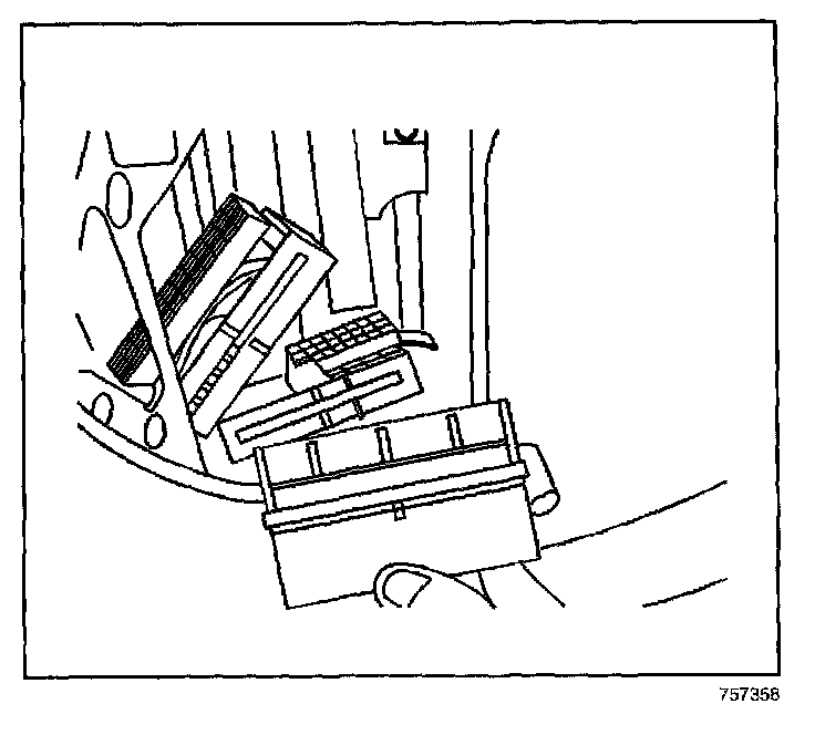
5. For the passenger side only:
5.1. Remove the IP storage compartment from the IP carrier.
5.2. Through the opening in the IP storage compartment, loosen the inboard junction block electrical connector bolts. Disengage the inboard junction block electrical connectors tabs from the IP fuse block.
5.3. Disengage the IP fuse block from the cross vehicle beam and remove the passenger side fuse block from the IP carrier.
5.4. Note where the fuses and relays are located and remove if required.
INSTALLATION PROCEDURE
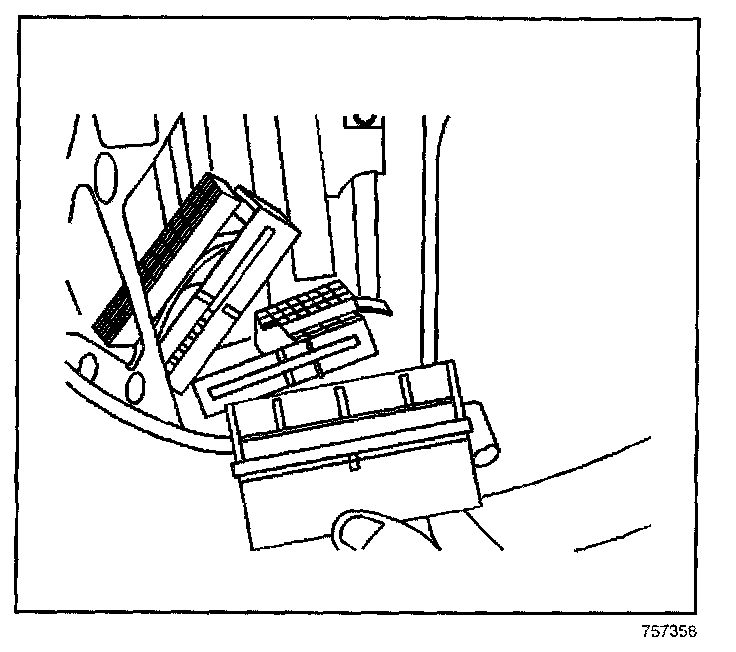
1. Install fuses and relays to the fuse block if required.
NOTE: Refer to Fastener Notice in Service Precautions.
2. For passenger side only:
2.1. Place the fuse block through the IP carrier.
2.2. Through the opening in the IP storage compartment connect the inboard junction block electrical connectors to the IP fuse block.
2.3. Engage the inboard junction block electrical connectors to the IP fuse block until the connector tabs are fully seated.
Tighten
Tighten the inboard junction block electrical connector bolts to 3 N.m (27 lb in).
2.4. Install the IP storage compartment to the IP carrier.
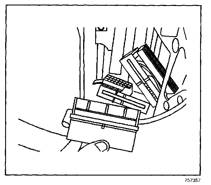
3. On the drivers side only:
3.1. Connect the inboard junction block electrical connectors to the IP fuse block.
3.2. Engage the inboard junction block electrical connectors to the IP fuse block until the connector tabs are fully seated.
Tighten
Tighten the inboard junction block electrical connector bolts to 3 N.m (27 lb in).
3.3. Engage the IP fuse block to the cross vehicle beam.
3.4. Engage the wire harness to the cross vehicle beam and install the left halve of the sound insulator to the IP carrier.
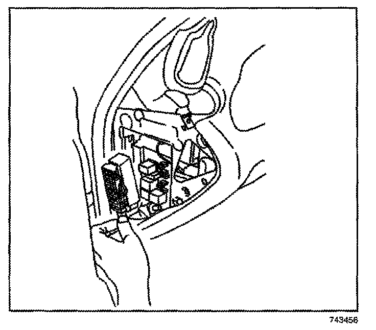
4. Install the outboard junction block electrical connector to the IP fuse block Left side shown, right side similar.
5. Engage the outboard junction block electrical connector to the IP fuse block until connector tabs are fully seated.
Tighten
Tighten the outboard junction block electrical connector bolt to 3 N.m (27 lb in).
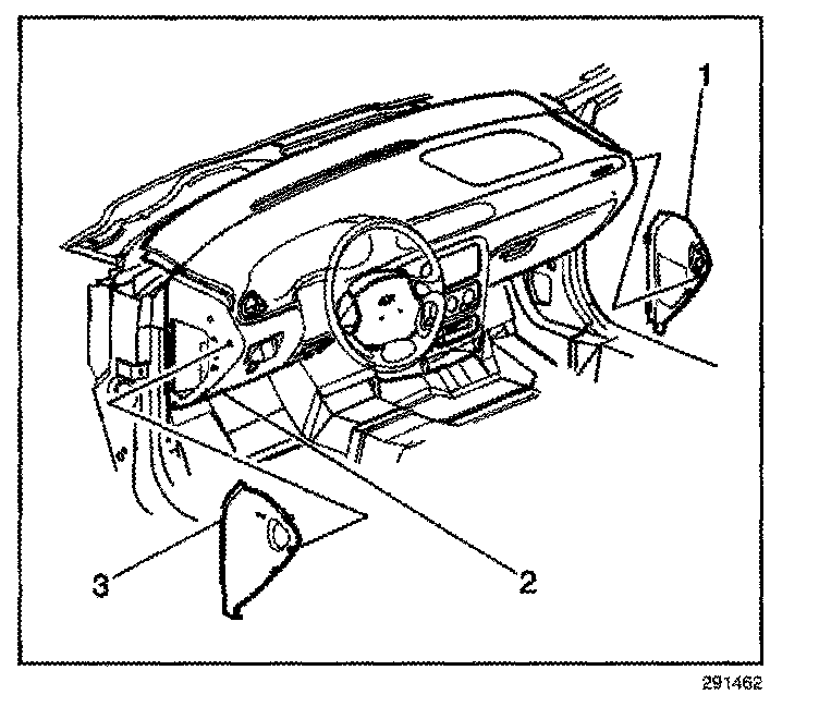
6. Install the outer trim covers (1, 3) to the Instrument Panel (IP) carrier (2).
7. Connect the negative battery cable.