Mode Door Replacement
REMOVAL PROCEDUREIMPORTANT: The defroster door must be closed to allow clearance during defroster duct removal.
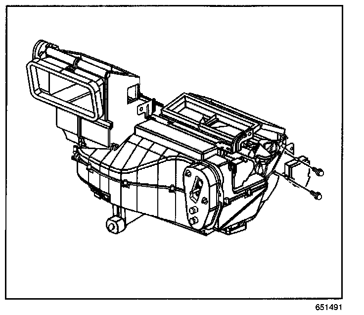
1. Set the HVAC controls in the VENT mode to close the defroster door.
2. Remove the IP carrier.
3. Disconnect the mode actuator connector.
4. Remove the mode actuator mounting screws.
5. Remove the mode actuator.
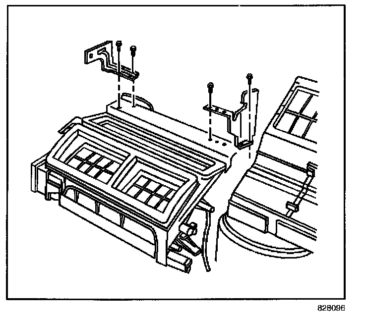
6. Remove the left HVAC module mounting bracket from the HVAC module assembly.
7. Remove the right HVAC module mounting bracket from the HVAC module assembly.
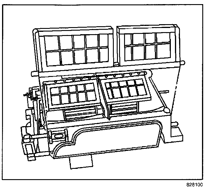
8. Remove the air temperature door and defroster door levers.
9. Remove the air distribution cover retaining screws.
10. Remove the air distribution cover.
11. Remove the mode door from the HVAC module assembly.
12. Remove the mode door levers from the mode door.
INSTALLATION PROCEDURE
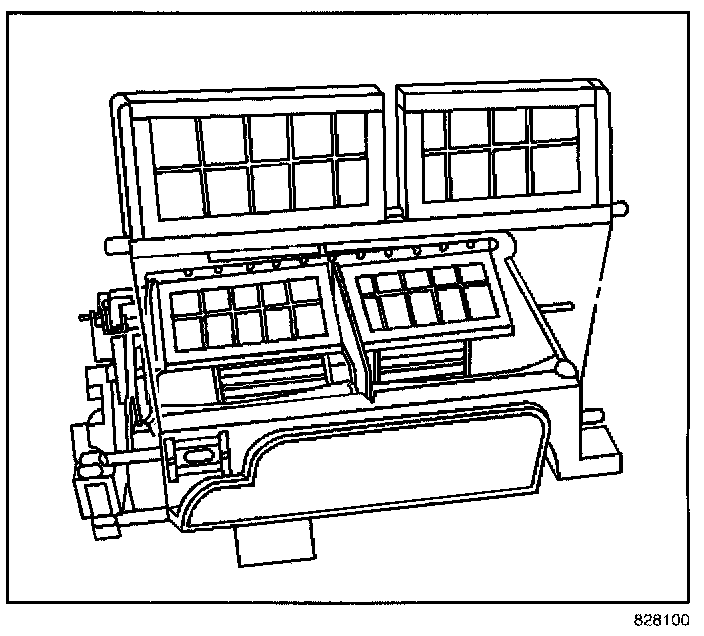
1. Install the mode door levers to the mode door.
IMPORTANT: Align the slot in the left mode door lever with the pin on the mode door main lever. Align the pin on the right mode door lever with the slot on the heater door lever.
2. Install the mode door.
3. Install the air distribution cover.
NOTE: Refer to Fastener Notice in Service Precautions.
4. Install the air distribution cover retaining screws.
Tighten
Tighten the screws to 0.9 N.m (8 lb in).
5. Install the air temperature door and defroster door levers.
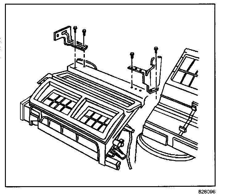
6. Install the right HVAC module mounting bracket to the HVAC module assembly.
7. Install the right HVAC module mounting bracket screws.
Tighten
Tighten the screws to 1.8 N.m (16 lb in).
8. Install the left HVAC module mounting bracket to the HVAC module assembly.
9. Install the left HVAC module mounting bracket screws.
Tighten
Tighten the screws to 1.8 N.m (16 lb in).
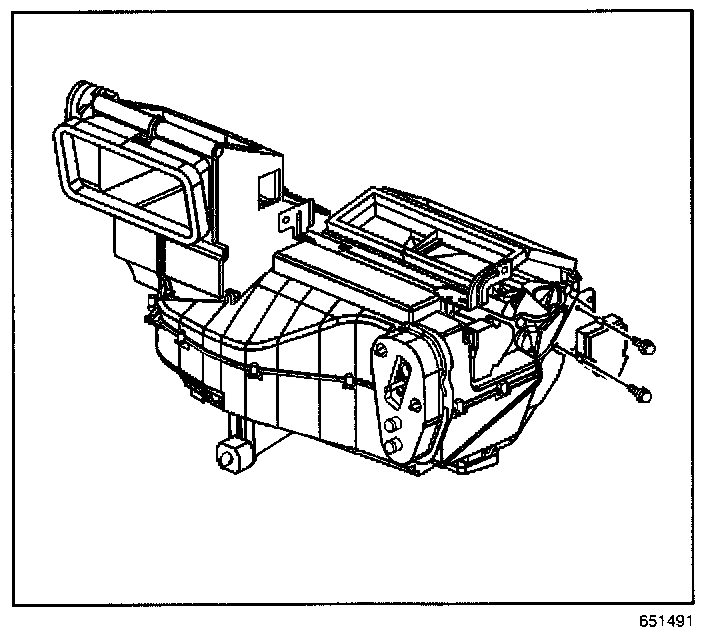
10. Install the mode actuator.
11. Install the mode actuator screws.
Tighten
Tighten the screws to 0.9 N.m (8 lb in).
12. Connect the mode actuator electrical connector.
13. Install the IP carrier.
14. If necessary, adjust the mode door linkage. Refer to Mode Linkage Adjustment.