Range Selector Displays Incorrect Range
Range Selector Displays Incorrect Range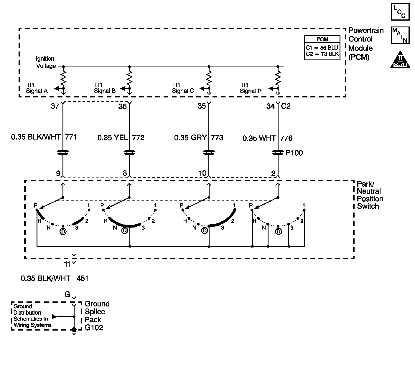
Circuit Description
The transmission range (TR) switch is part of the park/neutral position and back-up lamp switch assembly and is mounted on the transmission manual shaft. The TR switch is a multi-signal switch. The PCM supplies ignition voltage to the TR switch on four signal circuits, A, B, C, and P. Each gear selector lever position grounds one or more of the signal circuits in a unique pattern. In order to determine the gear range selected by the driver, the PCM compares the voltage combination on the signal circuits to a TR switch combination table stored in memory.
Diagnostic Aids
Refer to Transmission Range Switch Logic for valid combinations of switch signal circuits A, B, C and P.
Test Description
Steps 1 - 8:
Steps 9 - 15:
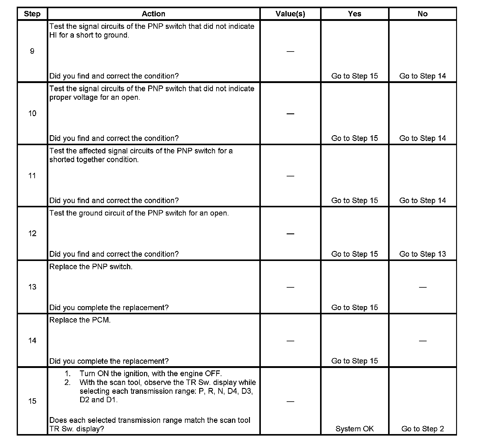
The numbers below refer to the step numbers on the diagnostic table.
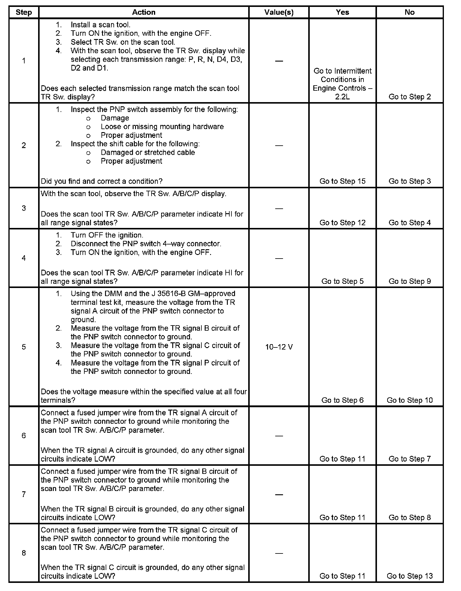
4. By disconnecting the TR switch, the ground path for all TR switch circuits would be removed and the PCM should recognize all circuits as open. The scan tool should display HI for all range signals.
5. This step tests the TR switch wiring for an open or lack of signal voltage from the PCM.
6. This step tests the TR switch wiring and the PCM by providing a ground path through a fused jumper wire. When grounded, the scan tool range signal A should change to LOW.
7. This step tests the TR switch wiring and the PCM by providing a ground path through a fused jumper wire. When grounded, the scan tool range signal B should change to LOW.
8. This step tests the TR switch wiring and the PCM by providing a ground path through a fused jumper wire. When grounded, the scan tool range signal C should change to LOW.