Steering Column
STEERING COLUMN REPLACEMENT
^ Tools Required
- J 41352 Modular Column Holding Fixture
Removal Procedure
Notice: Once the steering column is removed from the vehicle, the column is extremely susceptible to damage. Dropping the column assembly on the end could collapse the steering shaft or loosen the plastic injections, which maintain column rigidity. Leaning on the column assembly could cause the jacket to bend or deform. Any of the above damage could impair the columns collapsible design. Do NOT hammer on the end of the shaft, because hammering could loosen the plastic injections, which maintain column rigidity. If you need to remove the steering wheel, refer to the Steering Wheel Replacement procedure.
Notice: Do not support the steering column by only the lower or upper support bracket. Damage to the column lower bearing adapter could result.
Important: In the event of a deployment, inspect the coil wire for any of these signs of damage due to excessive heat:
^ Scorching
^ Melting
^ Other damage
Replace the coil, if necessary.
1. Disable the Restraints system. Service and Repair
Caution: Unless directed otherwise, the ignition and start switch must be in the OFF or LOCK position, and all electrical loads must be OFF before servicing any electrical component. Disconnect the negative battery cable to prevent an electrical spark should a tool or equipment come in contact with an exposed electrical terminal. Failure to follow these precautions may result in personal injury and/or damage to the vehicle or its components. For Vehicles equipped with OnStar (RPO UE1) with Back Up Battery: The Back Up Battery is a redundant power supply to allow limited OnStar functionality in the event of a main vehicle battery power disruption to the VCIM (OnStar module). Do not disconnect the main vehicle battery or remove the OnStar fuse with the ignition key in any position other than OFF. Retained accessory power (RAP) should be allowed to time out or be disabled (simply opening the driver door should disable RAP) before disconnecting power. Disconnecting power to the OnStar module in any way while the ignition is On or with RAP activated may cause activation of the OnStar Back-Up Battery (BUB) system and will discharge and permanently damage the back-up battery. Once the Back-Up Battery is activated it will stay on until it has completely discharged. The BUB is not rechargeable and once activated the BUB must be replaced.
2. Disconnect the negative battery cable. Service and Repair
3. Remove the steering wheel. Steering Wheel
4. Remove the left instrument panel insulator. Closeout/Insulator Panel Replacement - Left
5. Remove the trim panel below the steering column. Steering Column Filler
6. Remove the steering column knee bolster. Knee Bolster Bracket Replacement - Left
7. Remove the intermediate steering shaft from the steering column. Intermediate Steering Shaft
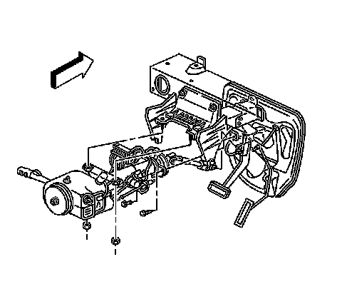
8. If equipped with a column shift lever, remove the park/lock cable from the ignition switch. Service and Repair
9. Disconnect the A/T range selector cable from the ball stud on the steering column.
10. Remove the transaxle shift cable casing from the steering column bracket by depressing the two tabs.
11. Disconnect the steering column electrical connectors.
12. Loosen the bolt on the steering column electrical connector.
13. Separate the two halves of the electrical connector.
14. Remove the lower steering column mounting bolts.
15. Remove the upper steering column mounting nuts.
Important: It may be necessary to spread the coupling clamp with a flat bladed tool in order to withdraw the steering shaft.
16. Remove the steering column from the vehicle.
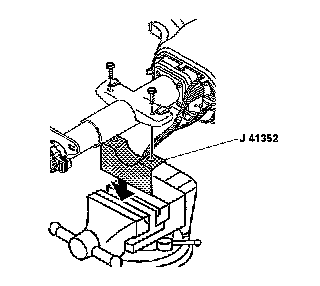
17. Install the steering column onto J 41352.
Installation Procedure
1. Remove the steering column from J 41352.
2. Position the steering column in the vehicle.
3. Insert the lower end of the steering column shaft into the intermediate steering shaft coupling. Intermediate Steering Shaft
4. Pull the intermediate shaft seal up over the lower column in order to lock the seal into place.
5. Connect the steering column electrical connectors.
6. Install the transaxle casing to the shift cam ball stud.
7. If equipped with a column shift lever, install the park/lock cable to the ignition switch. Service and Repair
Caution: When installing the steering column to the intermediate shaft, make sure that the shaft is seated prior to pinch bolt installation. If the bolt is inserted into the coupling before shaft installation, the two mating shafts may disengage.
8. Loosely install the upper and lower steering column fasteners.
Caution: In order to ensure the intended function of the steering column in a vehicle during a crash and in order to avoid personal injury to the driver:
^ Tighten the steering column lower fasteners before you tighten the steering column upper fasteners. Failure to do this can damage the steering column.
^ Tighten the steering column fasteners to the specified torque. Overtightening the upper steering column fasteners could affect the steering column collapse.
Notice: Use the correct fastener in the correct location. Replacement fasteners must be the correct part number for that application. Fasteners requiring replacement or fasteners requiring the use of thread locking compound or sealant are identified in the service procedure. Do not use paints, lubricants, or corrosion inhibitors on fasteners or fastener joint surfaces unless specified. These coatings affect fastener torque and joint clamping force and may damage the fastener. Use the correct tightening sequence and specifications when installing fasteners in order to avoid damage to parts and systems.
9. Tighten the steering column fasteners in this sequence:
a. Tighten the right side lower bolt to 24 Nm (18 ft. lbs.).
b. Tighten the left side lower bolt to 24 Nm (18 ft. lbs.).
c. Tighten the left side upper nut to 24 Nm (18 ft. lbs.).
d. Tighten the right side upper nut to 24 Nm (18 ft. lbs.).
10. Install the steering column knee bolster.
11. Install the trim panel below the steering column. Steering Column Filler
12. Install the left instrument panel insulator. Closeout/Insulator Panel Replacement - Left
13. Install the steering wheel. Steering Wheel
14. Install the SIR inflator module. Steering Wheel Module Replacement
15. Connect the negative battery cable. Service and Repair
16. Enable the Restraints system. Service and Repair
17. Inspect all of the steering column components for correct operation.